Download
1 / 88
930 likes | 1.26k Views
Explore the concepts of macro processing, loader schemes, and linking in a two-pass system. Learn about macro definition, nested calls, relocation, and advanced facilities for efficient program execution.

E N D
Macro Processor: Macro Definition and call, Macro Expansion, Nested Macro Calls and definition, Advanced Macro Facilities, Design of two-pass Macro Processor. Loaders: Loader Schemes, Compile and Go, General Loader Scheme, Absolute Loader Scheme, Subroutine Linkages, Relocation and linking concepts, Self-relocating programs, Relocating Loaders, Direct Linking Loaders, Overlay Structure. Unit-2 MACROPROCESSORS, LOADERS AND LINKERS
Unit-1 Loader and Linker • A program which accepts object program and prepares them for execution.
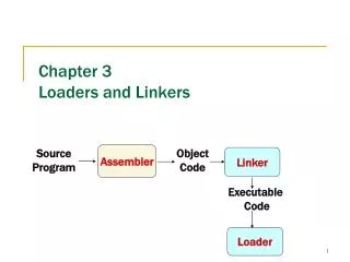
Basic Concept • object code, or an object file, is the representation of code that a compileror assemblergenerates by processing a source code file. • A linker is typically used to generate an executable file by linking object files together. • Object files often also contain data for use by the code at runtime, relocation information, program symbols (names of variables and functions) for linking and/or debugging purposes, and other debugging information.
Basic Concept… • In MS-DOS, Windows 95/98 etc object modules have extension .obj and the executable binary programs have .exe extension. In UNIX, object modules have .o extension and executable programs have no extens
Basic Functions of the Loader • ALLOCATION:Allocates space in memory for the programs( calculation program size) • RELOCATION: Adjustment of addresses of all address sensitive entities . • LINKING: Resolve inter-segment (inter-program) symbolic reference in object program. Linking of object modules with each other. • LOADING:Physically place the machine instructions and data into memory and initiate execution.
Loader Object program ready for execution Source Program Loader Assembler Fig.: Role of loader Memory
Loader • Loader is utility program which takes object code as input prepares it for execution and loads the executable code into the memory. • Thus loader is actually responsible for initiating the executions process.
Linking concepts • User defined function and library funtion • Example-printf() ,scanf() • The linking process makes address of modules known to each other so that transfer of control takes place during execution. • Passing of parameter is handled by the linker. • Public variable-same address • External variable –defined in one module and used in another module. • Resolving of addresses of symbolic reference is handled by the linker.
Linking concepts… • Linker- 1.Handled the passing of parameter 2.Resolving of address of symbolic reference
Relocation concepts • It is the process of modifying the addresses used in the address sensitive instructions of a program • So, program Can execute correctly from any designated area of memory. • Ex. MOVER AREG,X • Ex.:-Program A, call function F1(); • Program A and F1() must be linked with each other.
Relocation concepts Case I: Address assigned to Prog. A and F1 () when they translated to memory Drawback- a lot of storage area is wasted 0 100 250 400 500 A Wasted area F1 Fig.: General Loading scheme
Relocation concepts… Case II: These two module cannot co-exist at same storage locations. Main Storage 0 150 151 251 A 100 250 A F1 100 200 F1 Relocated address given by the loader Translation time address Fig.: Relocation to avoid address conflict or storage waste
Relocation concepts… • A loader must relocate A and F1 to avoid address conflict or storage waste. • Relocation refers to adjustment of address field not to movement of a program.
Loading Schemes… • Various types of loader ,based on various functionalities • Compile and go loader • General loader scheme • Absolute loader • subroutine linkage • Relocating loader • Direct linking loader
Loading Scheme Program modules A and B are loaded in memory after linking. It is ready for execution Object Module A A Loader B Object Module B Fig.: General Loading scheme
1.Compile and Go Loader • Performing the loader function is to have the assembler run in one part of memory and place the assembled machine instructions and data, as they are assembled,direcltly into their assigned memory location. • Diagram. • Also called “assemble and go”
Advantages: It is very simple to understand. It is simple to implement because loader is just an extension to the assembler design. 1.Compile and go loader….
1.Compile and go loader…. Disadvantages: • Portion of the memory is wasted because the assembler resides in the memory. • It is necessary to assemble every time even though no modifications are being done. • Can not handle multiple program segments especially if they are written in different languages (e.g. assembly lang. and FORTRAN or PL/I) • Scheme is good for small program not for bigger one • Execution time = assemble time + load time
2.General loader scheme • Diagram. • Loader places m/c instruction in memory. • Loader is smaller than assembler, so more memory is available to the user. • Advantage: 1.reassembly is no longer necessary to run the program. 2. Possible to write subroutine in several different lang.
3.Absolute Loader • An Absolute loader is the simplest of all other loaders. • It takes the output of Assembler and load into memory without relocation. • The output of the assembler can be stored on any machine readable form of storage, But most commonly it is stored on puched cards or magnetic tape, disk, or drum. • It loads a binary program in memory for Execution .
3.Absolute Loader…. • Binary program is stored in a file that contains: • Header records: Contains load Origin ,Length of code, load time execution starting address of program. • Transfer record: contains entry point of execution
Advantages: Simple, easy to design and implement Since more core memory is available the user, as an assembler is not memory at load time. No linking or relocation is efficient. Execution time = load time Absolute loader.
Absolute loader. • Disadvantages: • Programmer must specify the starting address to the assembler for the program where it should be loaded. • so programmer must know memory management as well as memory status at any time. • It is very difficult to relocate in case of multiple subroutine.
3.Absolute Loader • In absolute loader 4 loader function are performed by, • Allocation: by programmer • Linking: by programmer • Relocation: by assembler • Loading-by loader
Problem in Absolute loader…. • For Example: • Main() and SQRT( ) is loaded at memory location 150-300 bytes an 450-500bytes respectively. • If Main() will be modified it might be increase its size of code(may be more than 200 bytes) at that point Main() overlaps the content of SQRT(). • Since its MAIN() code size become 150+350=500 Which crosses the load origin of subroutine SQRT() which violets the scheme of absolute loader. • So,It is necessary to assign SQRT() to new location in the memory.
Absolute loader…. • For that its Start address have to be changed and re-assembling is required. • Also be necessarily to modify all other subroutines that referred to the address of SQRT();
Design of an Absolute Loader • Algorithm: • Begin • Read Header record • Verify program name and length • Read first text record • While record type <> ‘E’ do • Begin • { • If object code is in character form, convert into internal presentation • } • Move object code to specified location in memory. • Read next object program record. • End • Jump to address specified in end record • end
Subroutine Linkages/Program Linking Loader • Subroutine: In given program ,it is often needed to perform a particular subtask many times on different data values. such a subtask is usually called a subroutine. • Subroutine linkage method: The way in which a machine makes it possible to call and return from subroutine is referred to as its Subroutine linkage method
Subroutine Linkage • Subroutine Linkage: Instructions • There are two forms of the Branch and Link instruction. • BAL Branch and Link • BALR Branch and Link, Register.
Subroutine Linkage • Calling the subroutine • The format of the instruction is BAL Reg,Address • An example of such an instruction is BAL 8,P10PAGE • Returning from the subroutine • jump to an address contained in the register. • The format of the instruction is: BR Reg • An example of such an instruction is: BR 8
Example MAIN START EXTRN SUBROUT ------------- -------------- L 15,=A(SUBROUT) BALR 14,15 …. ….. END SUBROUT START USING *,15 ------------- -------------- BR 14 END
Relocating Loaders • Loader that allow for program relocation are called relocating loader/relative loader. • To avoid possible reassembling of all subroutines when a single subroutine is changed and to perform the tasks of allocation and linking for the programmer the relocating loader is created.
Relocating Loaders…. • Example: BINARY SYMBOLIC SUBROUTINE(BSS)loader used in the IBM 7094,IBM 1130,GE 635. • The output of a relocating assembler using a BSS scheme is the object program & information about all program it reference. • BSS loader scheme is used on computers with a fixed length direct address instruction format. • The BSS loader allows many procedure segments but only one data (common)segment.
Relocating Loaders… • Transfer Vector: that consists of address containing names of the subroutines referenced by the source program. • After loading the text and the transfer vector into core, the loader would load each subroutine identified in the transfer vector. • Thus the execution of the call SORT statement would result in branch to the first location in the transfer vector • The assembler would also provide the loader with additional information, such as the length of the entire program and the length of the transfer vector.
Relocating Loaders :Example MAIN START EXTERNAL SORT EXTERNAL ERR4 LOAD 1,=F9 BALINK 14,SQRT COMPARE 1,=F3 BNE ERR HLT =9 DATA 9 =3 DATA 3 END LC r / s / e 0 00 SORT 4 00 ERR 8 01 LOAD 1,1C C 01 BALINK 14, 0 10 01 COMPARE 1,20 14 01 BNE 4 18 00 HLT 1C 00 0009 20 00 0003
Relocating Loaders :After Loading Using BSS Scheme 0 400 BALINK 14,448 4 404 BALINK 14,526 8 408 LOAD 1,41C C 40C BALINK 14,400 10 410 COMPARE 1,420 14 414 BNE 404 18 418 HLT 1C 41C 0009 20 420 0003 • Program Length • 20 bytes • Transfer vector • 8 bytes
Relocating Loaders :Advantages • Relocation bits are used to solve the problem of relocation. • Transfer vector is used to solve the problem of linking & Program length info to solve allocation.
Relocating Loaders :DisAdvantages • No suited for loading external data. • Transfer vector increase the size. • Does not facilitate access to data segment that can be shared.
Direct linking loader: • It is type of Re-locatable Loader. • It is most common type of loader. • It allows the programmer to use multiple procedure segments and multiple data segments. • The assembler should give the following information to the loader: 1.The length of the object code segment. 2.A list of all symbols which are not defined in the current segment but can be used in the current segment.
Direct Linking Loader… 3.A list of all symbols which are defined in the current segment but can be referred in the current segment. 4.Information about address constants. 5.Machine code translation of the source program and relative address. • To place the object code in the memory there are two situations:1. Address of the object code could be absolute.2. The address of object code can be relative.
Direct linking loader: • The list of symbols not defined in the current segment but used in the current segment are stored in a data structure called USE table. • The lists of symbols defined in the current segment and referred by the other segments are stored in a data structure called DEFINITION table.
Assembler records • Assembler generates 4 types of cards in the object desk: • ESD:External Symbol Dictionary (ESD) record: • TXT: (TXT) records. • RLD: Relocation and Linkage Directory (RLD): • END :End of object deck
Assembler records…ESD 1.ESD:External Symbol Dictionary (ESD) record: Card contain information about all symbol that are defined in this program, but that may reference elsewhere, and all symbol referenced in this program but defined elsewhere.
Assembler records…ESD • Type: • SD: segment definition: symbol in segment • LD: Local definition: symbol is defined in this program but it can be referenced by other program. • ER: External symbol: defined in some external program.
Assembler records…TXT • 2. TXT: (TEXT) records. • Text card contains actual object code.(translated source code).