Download
1 / 22
220 likes | 373 Views
DITANET international conference ----Seville, Spain 9th-11th Nov. 2011. Design of an Electro-Optic Bunch Length Monitor for the CERN-CTF3 probe beam. R. Pan, T. Lefevre , S.P. Jamison, W.A. Gillespie CERN STFC Daresbury Laboratory University of Dundee. Outline. Introduction for Califes.

E N D
DITANET international conference ----Seville, Spain 9th-11th Nov. 2011 Design of an Electro-Optic Bunch Length Monitor for the CERN-CTF3 probe beam R. Pan, T. Lefevre , S.P. Jamison, W.A. Gillespie CERN STFC Daresbury Laboratory University of Dundee
Outline Introduction for Califes EOSD and Simulation Schemes and comparison Resolution Summary and Outlook
Introduction ---- CALIFES in a nutshell 3 single klystron Standing-wave photo-injector 4 4 to Two Beam Test Stand (TBTS) RF network 1 6 5 2 Complete set of diagnostics 3 travelling-wave structures (LIL) Existing bunch profile monitor: Deflecting cavity Bunch length measurement with the 12 GHz high gradient acceleration structure
Existing bunch profile monitors Deflecting cavity 12 GHz high gradient acceleration structure • Operating principle: • bunch pass at zero crossing in a deflecting cavity • bunch head experiences a transverse kick downward, bunch tail upward • bunch transverse size is then measured downstream on a beam profile monitor • Operating principle: • bunch pass at zero crossing in the accelerating structure (12 GHz – 100 MV/m) • bunch head is decelerated, bunch tail accelerated • Energy spread is measured downstream in the spectrometer line • Increase of energy spread is related to bunch length Tail Head Cavity OFF sy = 0.24 mm Cavity ON sy= 1.47 mm
Simulation: Coulomb field of e-bunch Coulomb field temporal profile β=0 β=0.9 β=0.9999 Coulomb field of one electron • High energy , Coulomb field temporal profile is approximately the bunch temporal profile • Broadening of profile:
Simulation: Coulomb field of e-bunch • Radial offset from single electron • Electrons’ density distribution within one bunch • Convolution Coulomb field temporal profile and broadening For high energy beam (>150 MeV): Broadening rate < 4% @ 10 mm 4%
Simulation: Coulomb field of e-bunch r0: the distance far away from e-bunch Damage to crystal Crystal survives, low Coulomb field Closer Further
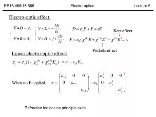
Simulation: EOSD Electro-Optical Spectral Decoding: • Linear chirped optical pulse • Polarization variation caused by Coulomb field—laser nonlinear effect • Polarization Intensity, by two crossed polarizers • I(λ) I(t) ----rotation matrix ----Jones matrix for quarter waveplate ----Jones matrix for half waveplate
Simulation: EOSD induce EO effect: Frequency mixing Polarization variation Coulomb field Laser Wider bandwidth, better resolution !
Simulation: EOSD results distortion Distortion: bunch length < 1 ps Other parameters: Laser wavelength: 780nm Laser pulse energy: 1.5nJ Pulse duration: 150fs Short bunch----fast temporal modulation---- spectral content ---- t~λ mapping Crystal thickness: 500μm Distance: 5mm
EO monitor Design for Califes • Stretcher: • SF11 glass • 100fs----3.24ps
Simulation: EOSD results Laser performance comparison Assume : Bunch charge = 0.2 nC, r0 = 5 mm Laser 1: Standard ytterbium fiber laser Laser 2: Standard erbium fiber laser Laser 3: Custom Er fiber laser with fiber transport Normal fiber: higher energy, not stable PM fiber: lower energy, stable Laser 4: Custom Er fiber laser with pulse picker pulse energy can be changed
EO monitor Design for Califes Extension part Streak Camera The hole to CLEX Optical table for testing and camera 2.25m Optical table for laser Streak Camera Controller 1 m 4 m • Laser room safety • An interlock shutter is needed for the laser room. When the door of the lab is opened, laser will be blocked automatically by the interlock shutter. • When the laser is running, people in the lab should wear laser protection glasses. • Signs (usually these are lights) should be both inside and outside of the lab to warn people that the laser is running. • Follow the safety rules of laser room at CERN. • Laser room extension Height: 2.62 m
EO monitor Design for Califes Laser Transport Line
EO monitor Design for Califes Chamber design ① Adjustable arm ② Observation port ③ Laser input/output viewport ④ Central chamber
Operation and Commissioning Motors and Observers ICCD gated camera Laser Chambers • Synchroniz-ation • Timing : phase shifter and delay stage • Controlled from the laser lab • Controlled in laser lab • Trigger signal: beam loss monitor around chamber • Controlled in CTF3 control room
Expected Resolution 1. Distance between crystal and e-beam ~10 fs at r=5 mm 2. The frequency response of crystal (material and thickness) for 1 mm ZnTe: ~333 fs ~1/(3THz) 3. EOSD limitation (Laser pulse duration and chirped duration) ~550 fs (100 fs3 ps) 4. Resolution of spectrometer and CCD ~40 fs (512 pixels) Grating
Summary & Outlook Summary: EO system scheme and Laser room are prepared. All the optical items are ordered. Based on numerical simulation, the resolution of this system is expected to be sub-picosecond. A EO bunch length measurement system will be installed at CTF3 in the summer of 2012. Outlook: Build up the optical system and continue to do experiments based on frequency up-conversion method and other new methods for resolution improvement. This research project has been supported by a Marie Curie Early Initial Training Network Fellowship of the European Community’s Seventh Framework Programme under contract number (PITN-GA-2008-215080-DITANET)
References [1] X. Yan, A. M. MacLeod, W. A. Gillespie, G. M. H. Knippels, D. Oepts, A. F. G. van der Meer and W. Seidel, Phys. Rev. Lett. 85, 3404 (2000). [2] I. Wilke, A. M. MacLeod, W. A. Gillespie, G. Berden, G. M. H. Knippels, and A. F. G. van der Meer, Phys. Rev. Lett. 88, 124801 (2002). [3] A. Azima, S. D¨usterer, H. Schlarb, J. Feldhaus, A. Cavalieri, D. Fritz, and K. Sengstock, In Proceedings of the EPAC 2006, Edinburgh, Scotland, 2006, p. 71. [4] G. Berden, S. P. Jamison, A. M. McLeod, W. A. Gillespie, B. Redlich, and A. F. G. van der Meer, Phys. Rev. Lett. 93, 114802 (2004). [5] S. P. Jamison, G. Berden, P. J. Phillips, W. A. Gillespie, and A. M. MacLeod, Appl. Phys. Lett. 96, 231114 (2010). [6] J. D. Jackson. Classical Electrodynamics (John Wiley and Sons, Inc., 1999). [7] S. P. Jamison, A. M. MacLeod, G. Berden, D. A. Jaroszynski, W. A. Gillespie, Opt. Lett. 31, 1753 (2006). [8] S.P. Jamison, G. Berden, W.A. Gillespie, P.J. Phillips, A.M. MacLeod, in Proceedings of EPAC08, Genoa, Italy, 2008, p. 1149. [9] J. Breunlin, Diploma thesis, University Hamburg, 2011. [10] B.Steffen et al., Phys. Rev. ST Accel. Beams 12, 032802 (2009). [11] A. Yariv. Quantum electronics (1989).
CTF3 – Layout DELAY LOOP COMBINERRING 4 A – 1.2 ms 150 Mev DRIVE BEAM LINAC 28 A – 140 ns 150 Mev Two-Beam Test Stand (TBTS) Test Beam Line (TBL) CLEX CLIC EXperimental Area 10 m
Simulation: EOSD results Laser performance comparison The photon numbers we can get with different kinds of laser source. Assume bunch charge is 0.2 nC, distance r0 is 5 mm away from beam and the thickness of crystal is 500 μm for ZnTe. The angle of HWP is 1.4 degrees while QWP is at 0 degrees. *Optical loss: