Download
1 / 11
110 likes | 121 Views
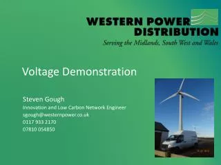
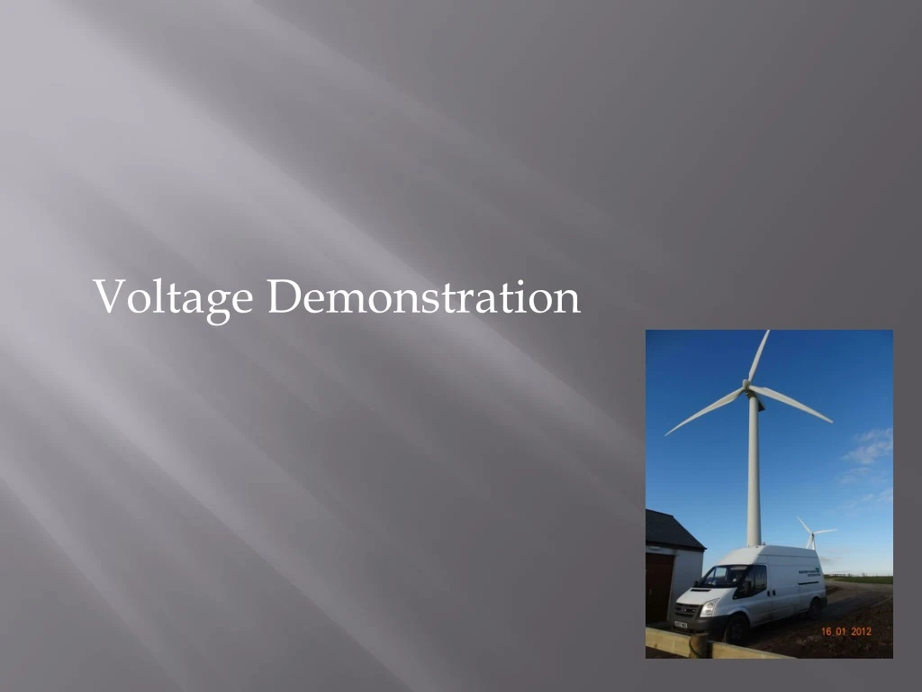
Voltage Demonstration. Introduction. Background Aims Progress in Phase 1 Phase 1 output graphs Plans for Phase 2 Learning so far. Background. D-SVC - Static VAr Compensator for Distribution Networks Supplied by Hitachi Can produce 400kVAr leading or lagging

E N D
Introduction • Background • Aims • Progress in Phase 1 • Phase 1 output graphs • Plans for Phase 2 • Learning so far
Background • D-SVC - Static VAr Compensator for Distribution Networks • Supplied by Hitachi • Can produce 400kVAr leading or lagging • 11kV connected via a dedicated 11kV/415V transformer • Designed for use on long rural feeders that have Distributed Generation (DG) for voltage control
Aims • Stabilise voltage for a windfarm at the end of a 11kV feeder • Establish the impact of the D-SVC on the 11kV network • Test the three different modes available on the D-SVC • Voltage Regulation • Voltage Averaging • Short Term Fluctuations
D-SVC Progress in Phase 1 • D-SVC is installed on site adjacent to a 1.5MW windfarm in Cornwall • Protection was installed on the LV side of the transformer as there was not a metering unit • Monitoring equipment was installed along the feeder • D-SVC has been running on various modes for nearly 4 months Roskrow WF G Kernick Industrial Estate Summerheath Bickland Hill Primary
D-SVC G D-SVC D-SVC Plans for Phase 2 • Three D-SVCs will be used across two adjacent primary substations • A D-VQC (Voltage and Reactive Power (Q) Control System) will be used at the primary to control all three D-SVCs and the tap changer at one of the primary substations • Although the site has not been confirmed, there is a combinations of medium wind generation, very long rural feeders and a large number of domestic properties with PV
Learning so far • When setting up a protection of the D-SVC the protection needs to be on the HV side of the transformer • When sizing the transformer for a D-SVC it is important select well above the power requirement of the device • The D-SVC can help smooth the voltage • The D-SVC can help reduce the range of voltages see on the 11kV
Any Questions? Steven Gough Innovation and Low Carbon Network Engineer sgough@westernpower.co.uk 0117 933 2170 07810 054850