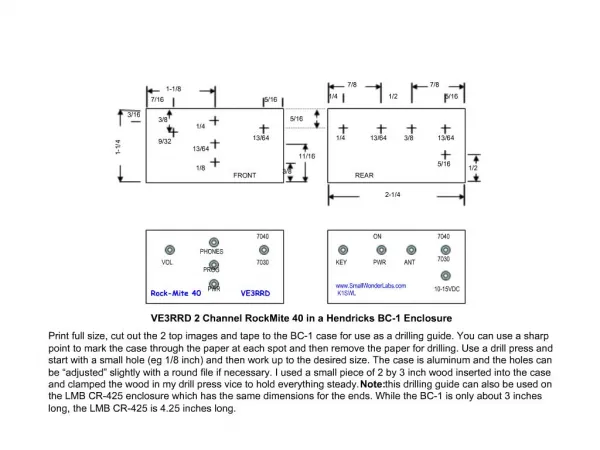
Download
1 / 36
360 likes | 362 Views
This text discusses the angular dispersion in optical devices such as prisms and gratings, and its relation to group velocity dispersion (GVD). It also explores the adjustable parameters for pulse stretching and compression using prisms and grating pairs.

E N D
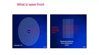
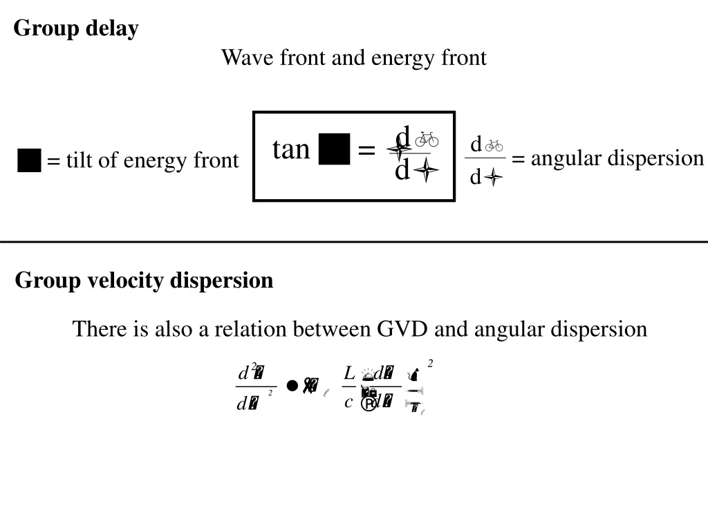
Group delay Wave front and energy front db tan g = l db = angular dispersion g = tilt of energy front dl dl Group velocity dispersion There is also a relation between GVD and angular dispersion
S’W Q S0, SW PW rW a L r0 P0 S’0 Whether considering group delays or group velocity dispersion (GVD), we will consider sufficiently broad beams, and sufficiently short propagation distances Lp behind the element, such that diffraction effects can be neglected.
S’W Q S0, SW PW rW a L r0 P0 S’0
The most widely used optical devices for angular dispersion are prisms and gratings. To determine the dispersion introduced by them we need to specify not only a(W), but also the optical surfaces between which the path is being calculated. The ``dispersion'' of an element has only meaning in the context of a particular application, that will associate reference surfaces to that element.
a h a L A B L g C (R)
The stability of the cavity requires that R > L implying that the coefficients a and b are positive. Therefore, in a cavity with a single prism as sketched the group velocity dispersion is adjustable through the parameter h, but always positive.
First mode-locked laser with negative phase modulation and positive adjustable dispersion: Intracavity pulse compression with glass: a new method of generating pulses shorter than 60 fsec OPTICS LETTERS / Vol. 8, No. 1 / January 1983 dispersion Phase modulation
For a collimated beam, a logical reference plane is normal to the beam Pairs of prisms 2nd Element (reversed) Reference plane B Reference plane A 1st Element
Prism arrangement from the Diels group: How to check that the prisms are correct? Minimum deviation Material? Brewster angle? Alignment?
A d q4 q3 q2 q1 p-A
The group velocity dispersion is simply the sum of three contributions: 1. The (positive) GVD due to the propagation of the pulse through a thickness of glass Lg. 2. The negative GVD contribution due to the angular dispersion over the path between prisms 3. The negative GVD contribution due to the angular dispersion -- deflection of the beam at the first interface Lg in the glass of index n. For Brewster angle prisms at minimum deviation angle:
O H A q0 q3 B q2 q1 D t2 W t W+dW q6 q4 q5 q0 B’ = q3 A’ A’’ a u O’ s
O q3 A B q2 t q4 B’ A’ W = q3 A’’ t2 W+dW a O’ s
dq3 q6 q5 q7 = q0 B’ A’ Q a-q2 R B’’ T A’’ S q5 u q4 H’ B’’’ A’’’ a O’
W O a X A’ q0 A W + dW q1 dq1 A’’ q1 O’’’ g
ceo Phase delay { For a pair of prisms we found: For gratings, the simple rule applies also
C P d b’ b b A
Pulse stretching/compression with prisms and grating pairs 1. Devices for adjustable dispersion: Prisms and gratings 2. GVD of prisms pairs 3. GVD of gratings pairs 4. Gratings pairs for pulse stretching – what are the adjustable Parameters? 5. Application: Pulse shaping by “spectral filtering” 6. Can we have positive GVD with grating pairs?
4. Gratings pairs for pulse stretching – what are the adjustable Parameters? Wavelength? l Fixed Groove spacing d? Larger than l Diffraction angle large (Littrow configuration) Size of grating: pulse length.
Short pulse lasers phase modulation – Dispersion solitons dispersion Phase modulation Mode-locking = putting modes in phase AO modulator (active mode-locking) Role of saturable absorber.
Saturable absorbers: Liquid dye jets Multiple quantum wells.
Saturable absorbers: Liquid dye jets Multiple quantum wells.
145.5 nm 0.5 mm LT In0.25Ga0.75 As GaAs substrate GaAs GaAs GaAs ... GaAs GaAs GaAs GaAs AlAs AlAs 21 pairs Low Temp. growth (350o C, not annealed) Thickness: AlAs 90.5 nm GaAs 76.2 nm (last layer 145.5 nm) Thickness: InGaAs 15 nm GaAs 138.7 nm (last layer 69.3 nm) (first layer included in the 145.5 nm) Substrate: both sides polished LT In0.25Ga0.75 As GaAs substrate MQW for 1064 nm GaAs GaAs GaAs GaAs GaAs GaAs Low Temp. growth (350o C, not annealed) Thickness: InGaAs 14 nm GaAs 133.6 nm (last layer 66.8 nm)
Electric field amplitude time 0 Equally spaced modes in phase, make pulses periodic in time
Direct creation of a frequency comb A perfectly regular frequency comb is formed by nonlinear optics: w, 2w, 3w, 4w, 5w, ... But they are not in phase. If they can be put in phase, a pulse train with zero CEO is created. Reference:
w 2w 3w 4w W 5w Direct creation of a frequency comb 4w 5w 3w 2w w LASER Pulse duration tRT Mode bandwidth Number of pulses CEO? CEP?
Short pulse lasers Putting cavity modes in phase Active Passive Saturable absorbers Dispersion – Kerr modulation
The real thing: the laser Tuning the wavelength, the mode and the CEO L. Arissian and J.-C. Diels, “Carrier to envelope and dispersion control in a cavity with prism pairs”, Physical Review A, 75:013824 (2007).
Dilemma: If there is dispersion, the modes are not equally spaced!
D Mode locked laser l FREQUENCY TUNABLE LASER MODE-LOCKED LASER SPECTROMETER Frequency counter FREQUENCY COUNTER Round -trip frequency 200 101 884 000 Hz - 100 ORTHODONTIST wavelength Rep. Rate 700 800 900 Wavelength [nm] The laser as an orthodontist Tuned cw laser