Download

1 / 8
80 likes | 234 Views
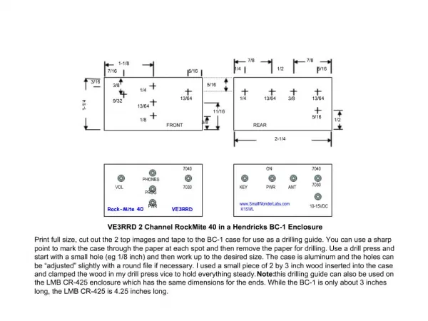
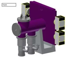
BESS – 6.7 kW Module Photo & Drawing. Top. 735 mm. 360 mm. 1210 mm. 100 mm. Front. Right. 6.7 kW BESS Specification. Note: * by embedded charger. External charger can be used for quick charging. DC. BESS – 6.7 kW Module Block Diagram. LCD Display, Lamps, & Emergency SW.

E N D
BESS – 6.7 kW Module Photo & Drawing Top 735 mm 360 mm 1210 mm 100 mm Front Right
6.7 kW BESS Specification Note: * by embedded charger. External charger can be used for quick charging DC
BESS – 6.7 kW Module Block Diagram LCD Display, Lamps, & Emergency SW Lithium Polymer Battery Cell Module Stack Current Sensor to BMS RS 485 MC 4 BMS Board Power Board MC 3 RS 485 MC 2 DC/AC INVERTER Current Sensor to Inverter MC 5 Bypass Frame Ground MC 1 MCCB H E A T E R AC mains from grid AC output to load From PV Power Conditioner
, , BESS 3.1 KW/6.7 kW – Power Flow & LCD Display Current Sensor Load AC Grid MC BMS Inverter BMS MC DC/AC INVERTER BATTERY OP Mode 02:20 July 02 2010 Current Time A 3.0 kW 0.3 kW AC Main Load AC Main Output Fan Heater 2.7 kW 2.5 kWh PV BESS SOC Inverter Output SOH 80% SOL 80%
Ruby Active BMS Features • RTC Scheduler • Operation by programmed schedule • Time stamp by event • Computation & Measurement • Charge/discharge coulomb counting • Cell internal resistance measurement • SOH (State of Health), SOC (State of Charge) • Cell module control • Charge control by CC/CV method • Cell module shutdown – Zero standby current • Cell history by cell module • Communication • Ethernet/TCP/IP – Remote analysis, program down load • External charger control via RS485 • Inverter control via RS485 • Inter BMS communication via RS485 • Display & Control • LED display & control/data input terminal • 3.5 inch TFT LCD / touch screen • BESS management • UPS system mode control by RTC – Mode A, B, C, power failure mode • Ignition key / power switch • Emergency • Shutdown mode • GPIO MC – 10 unit
Comparison Test Report – Ruby BMS vs. Passive BMS Cell Balancing by Active BMS, Ruby™ (Korea) Cell Balancing by Passive BMS, R company (UK) Test with deliberately unbalanced cells Cell Balancing by Passive BMS, N company (Korea)
Comparison BESS Performance – Ruby BMS vs. Passive BMS Bank 1 with BMS 1 Bank 2 with BMS 2 Bank n with BMS n BESS Total Cell voltage level by Active BMS 4.20 All cells are balanced with Active BMS 4.10 Non Usable Capacity with Passive BMS 4.00 Energy Waste by Passive BMS 3.90 All cells are not balanced with Passive BMS 3.80 Cell voltage level by passive BMS 3.70 After Bank Connection 1 2 3 4 5 --- -- L 1 2 3 4 5 ---- M 1 2 3 4 5 ---- N 1 2 3 4 5 ---- K Cell balancing by Active BMS Cell balancing by passive BMS