Download

1 / 21
210 likes | 226 Views
Disks. The Memory Hierarchy. Each level acts as a cache for the layer below it. CPU. registers, L1 cache. L2 cache. primary memory. disk storage (secondary memory). random access. tape or optical storage (tertiary memory). sequential access. What does the disk look like?.

E N D
The Memory Hierarchy • Each level acts as a cache for the layer below it CPU registers, L1 cache L2 cache primary memory disk storage (secondary memory) random access tape or optical storage (tertiary memory) sequential access
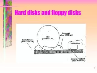
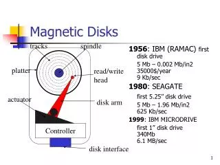
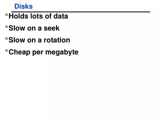
Some parameters • 2-30 heads (platters * 2) • diameter 14’’ to 2.5’’ • 700-20480 tracks per surface • 16-1600 sectors per track • sector size: • 64-8k bytes • 512 for most PCs • note: inter-sector gaps • capacity: 20M-100G • main adjectives: BIG, slow
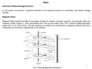
Disk overheads • To read from disk, we must specify: • cylinder #, surface #, sector #, transfer size, memory address • Transfer time includes: • Seek time: to get to the track • Latency time: to get to the sector and • Transfer time: get bits off the disk Track Sector Rotation Delay Seek Time
Smallest write: sector Atomic write = sector Random access: 5ms not on a good curve Sequential access: 200MB/s Cost $.002MB Crash: doesn’t matter (“non-volatile”) Disks vs. Memory • (usually) bytes • byte, word • 50 ns • faster all the time • 200-1000MB/s • $.10MB • contents gone (“volatile”)
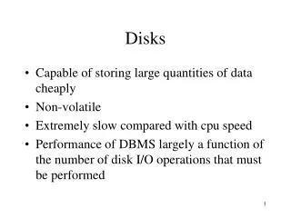
Disk Structure • Disk drives addressed as 1-dim arrays of logical blocks • the logical block is the smallest unit of transfer • This array mapped sequentially onto disk sectors • Address 0 is 1st sector of 1st track of the outermost cylinder • Addresses incremented within track, then within tracks of the cylinder, then across cylinders, from innermost to outermost • Translation is theoretically possible, but usually difficult • Some sectors might be defective • Number of sectors per track is not a constant
Non-uniform #sectors / track • Maintain same data rate with Constant Linear Velocity • Approaches: • Reduce bit density per track for outer layers • Have more sectors per track on the outer layers (virtual geometry)
Disk Scheduling • The operating system tries to use hardware efficiently • for disk drives having fast access time, disk bandwidth • Access time has two major components • Seek time is time to move the heads to the cylinder containing the desired sector • Rotational latency is additional time waiting to rotate the desired sector to the disk head. • Minimize seek time • Seek time seek distance • Disk bandwidth is total number of bytes transferred, divided by the total time between the first request for service and the completion of the last transfer.
Disk Scheduling (Cont.) • Several scheduling algos exist service disk I/O requests. • We illustrate them with a request queue (0-199). 98, 183, 37, 122, 14, 124, 65, 67 Head pointer 53
FCFS Illustration shows total head movement of 640 cylinders.
SSTF • Selects request with minimum seek time from current head position • SSTF scheduling is a form of SJF scheduling • may cause starvation of some requests. • Illustration shows total head movement of 236 cylinders.
SCAN • The disk arm starts at one end of the disk, • moves toward the other end, servicing requests • head movement is reversed when it gets to the other end of disk • servicing continues. • Sometimes called the elevator algorithm. • Illustration shows total head movement of 208 cylinders.
C-SCAN • Provides a more uniform wait time than SCAN. • The head moves from one end of the disk to the other. • servicing requests as it goes. • When it reaches the other end it immediately returns to beginning of the disk • No requests serviced on the return trip. • Treats the cylinders as a circular list • that wraps around from the last cylinder to the first one.
C-LOOK • Version of C-SCAN • Arm only goes as far as last request in each direction, • then reverses direction immediately, • without first going all the way to the end of the disk.
Selecting a Good Algorithm • SSTF is common and has a natural appeal • SCAN and C-SCAN perform better under heavy load • Performance depends on number and types of requests • Requests for disk service can be influenced by the file-allocation method. • Disk-scheduling algo should be a separate OS module • allowing it to be replaced with a different algorithm if necessary. • Either SSTF or LOOK is a reasonable default algo