Download
1 / 17
180 likes | 325 Views
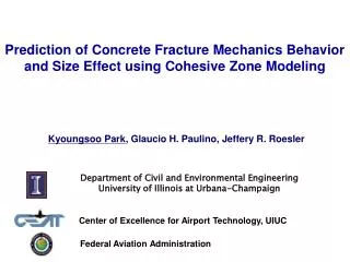
Modeling Fracture in Elastic-plastic Solids Using Cohesive Zone. CHANDRAKANTH SHET Department of Mechanical Engineering FAMU-FSU College of Engineering Florida State University Tallahassee, Fl-32310. Sponsored by US ARO, US Air Force. Fracture/Damage theories to model failure.

E N D
Modeling Fracture in Elastic-plastic Solids Using Cohesive Zone CHANDRAKANTH SHET Department of Mechanical Engineering FAMU-FSU College of Engineering Florida State University Tallahassee, Fl-32310 Sponsored by US ARO, US Air Force
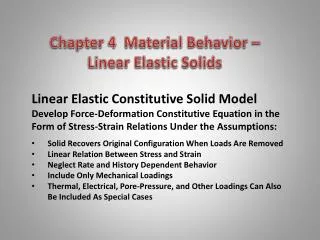
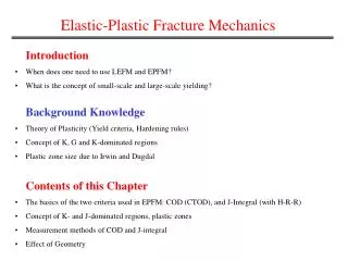
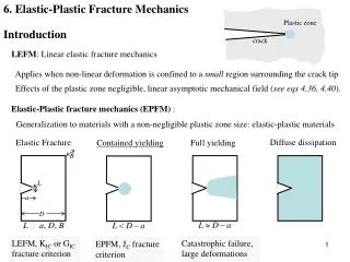
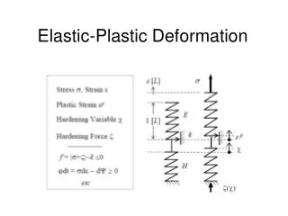
Fracture/Damage theories to model failure • Fracture Mechanics - • Linear solutions leads to singular fields-difficult to evaluate • Fracture criteria based on • Non-linear domain- solutions are not unique • Additional criteria are required for crack initiation and propagation • Basic breakdown of the principles of mechanics of continuous media • Damage mechanics- • can effectively reduce the strength and stiffness of the material in an average sense, but cannot create new surface
CZM is an Alternative method to Model Separation • CZM can create new surfaces. Maintains continuity conditions mathematically, despite the physical separation. • CZM represent physics of fracture process at the atomic scale. • It can also be perceived at the meso-scale as the effect of energy dissipation mechanisms, energy dissipated both in the forward and the wake regions of the crack tip. • Uses fracture energy(obtained from fracture tests) as a parameter and is devoid of any ad-hoc criteria for fractureinitiation and propagation. • Eliminates singularity of stress and limits it to the cohesive strength of the the material. • Ideal framework to model strength, stiffness and failure in an integrated manner. • Applications: geomaterials, biomaterials, concrete, metallics, composites…
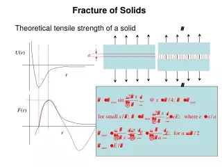
Development of CZ Models-Historical Review Figure (a) Variation of Cohesive traction (b) I-inner region,II-edge region • Molecular force of cohesion acting near the edge of the crack at its surface (region II ). • The intensity of molecular force of cohesion ‘f ’ is found to vary as shown in Fig.a. • The interatomic force is initially zero when the atomic planes are separated by normal intermolecular distance and increases to high maximum after that it rapidly reduces to zero with increase in separation distance. E is Young’s modulus and is surface tension • Barenblatt(1959)was first to propose the concept of Cohesive zone model to brittle fracture (Barenblatt, G.I, (1959), PMM (23) p. 434)
Phenomenological Models • The theory of CZM is based on sound principles. • However implementation of model for practical problems grew exponentially for practical problems with use of FEM and advent of fast computing. • Model has been recast as a phenomenological one for a number of systems and boundary value problems. • The phenomenological models can model the separation process but not the effect of atomic discreteness. • Hillerborg etal. 1976 Ficticious crack model; concrete • Bazant etal.1983 crack band theory; concrete • Morgan etal. 1997 earthquake rupture propagation; geomaterial • Planas etal,1991, concrete • Eisenmenger,2001, stone fragm- • entation squeezing" by evanescent waves; brittle-bio materials • Amruthraj etal.,1995, composites • Grujicic, 1999, fracture beha-vior of polycrystalline; bicrystals • Costanzo etal;1998, dynamic fr. • Ghosh 2000, Interfacial debo-nding; composites • Rahulkumar 2000 viscoelastic fracture; polymers • Liechti 2001Mixed-mode, time-depend. rubber/metal debonding • Ravichander, 2001, fatigue • Tevergaard 1992 particle-matrix interface debonding • Tvergaard etal 1996 elastic-plastic solid :ductile frac.; metals • Brocks 2001crack growth in sheet metal • Camacho &ortiz;1996,impact • Dollar; 1993Interfacial debonding ceramic-matrix comp • Lokhandwalla 2000, urinary stones; biomaterials
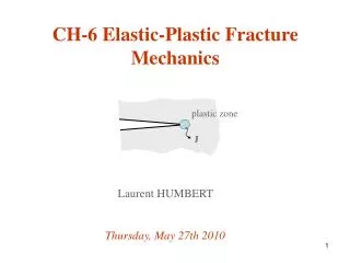
Fracture process zone and CZM Mathematical crack tip Material crack tip x • CZM essentially models fracture process zone by a line or a plane ahead of the crack tip subjected to cohesive traction. • The constitutive behavior is given by traction displacement relation, obtained by defining potential function of the type y where are normal and tangential displacement jump The interface tractions are given by
Following the work of Xu and Needleman (1993), the interface potential is taken as where are some characteristic distance Normal displacement after shear separation under the condition Of zero normal tension • Normal and shear traction are given by
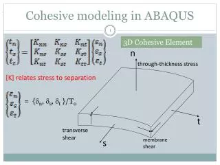
Numerical Formulation Continuum elements • The numerical implementation of CZM for interface modeling with in implicit FEM is accomplished developing cohesive elements • Cohesive elements are developed either as line elements (2D) or planar elements (3D)abutting bulk elements on either side, with zero thickness 1 2 3 4 • The virtual work due to cohesive zone traction in a given cohesive element can be written as 5 6 Cohesive element 7 8 The virtual displacement jump is written as Where [N]=nodal shape function matrix, {v}=nodal displacement vector J = Jacobian of the transformation between the current deformed and original undeformed areas of cohesive surfaces Note: is written as d{T}- the incremental traction, ignoring time which is a pseudo quantity for rate independent material
Numerical formulation contd The incremental tractions are related to incremental displacement jumps across a cohesive element face through a material Jacobian matrix as For two and three dimensional analysis Jacobian matrix is given by Finally substituting the incremental tractions in terms of incremental displacements jumps, and writing the displacement jumps by means of nodal displacement vector through shape function, the tangent stiffness matrix takes the form