Download
1 / 38
420 likes | 801 Views
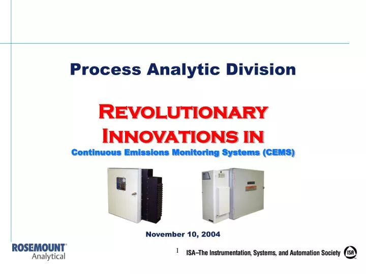
Process Analytic Division Revolutionary Innovations in Continuous Emissions Monitoring Systems (CEMS) November 10, 2004. Introduction. Continuous Emissions Monitoring Systems (CEMS) are vital in power plant and process industries.

E N D
Process Analytic Division Revolutionary Innovations in Continuous Emissions Monitoring Systems (CEMS) November 10, 2004
Introduction • Continuous Emissions Monitoring Systems (CEMS) are vital in power plant and process industries. • These systems traditionally cause facilities to endure high installation and maintenance costs. • However, revolutionary innovations now present significant cost-saving opportunities to CEMS users.
Traditional CEMS Requirements • A sampling probe mounted at the appropriate height on a stack • A heated sample line to transport moisture-laden gas samples to the analysis station • A shelter building erected and maintained to provide the proper operating environment for the analysis equipment • A programmable logic controller (PLC) to manage the monitoring process • A suitable data acquisition system (DAS) to generate data, reports and records • Installation costs up to $150,000 or more per stack
New Innovative CEMS • Recent CEMS advancements allow emission monitoring accuracy and data handling at a significantly lower cost than with systems created from discrete components through innovations like: • Direct stack/duct enclosure mounting • Split systems • Smaller enclosures • Reduced enclosure power requirements • Plug and Play Ethernet Web-browser interfaces
CEMS Designs Streamlined Field- Mount Approach $75K Cabinet Approach $95K Shelter Approach $150K
Direct Enclosure Mounting • The elimination of a heated sample line between a sample probe and a sample conditioning/analysis system can create significant cost savings and save considerable headaches and process downtime or violations because: • The installed cost of heated sample lines is about $100 per foot (the average 150-foot line costs about $15,000). • Sample lines are delicate, require skilled installers and are often damaged during installation. • Sample lines require diligent maintenance on the sample probe. • Process upsets or process equipment failures can sometimes lead to plugging of the sample line, necessitating its replacement. • Heated sample lines are long lead-time items, often taking weeks to procure even in emergency situations.
Direct Enclosure Mounting (con’t.) • Real-time measurements are important for timely feedback on critical emission levels. • With long sample lines the analysis process is delayed, causing potentially harmful delays in emission level corrections. • However, close-coupled or direct mounting of sample handling and analysis enclosures eliminates the need for a sample line and provides the following advantages: • Reduced transport time for sample reading, providing a near-real-time measurement signal • Faster, continuous measurement for efficient pollution reduction system control, quicker adjustments, and reduced emission limits violations • Elimination of heated sample lines, providing energy savings as they typically use 25-50% of energy consumed by the CEMS
CEMS Installation Sample handling installed at the probe No heat trace lines required Analyzer mounted outside
Split Systems • Newer CEMS feature a split system architecture of: • A sample handling system (probe and conditioning station) • Analysis components • With sample handling systems mounted on the stack or duct, analysis components can be mounted at: • Stack • Base of stack • Ground level • Remote buildings • Other easy to access areas
Ground Level Installation – Optional Probe Only All Sample Handling located at base of stack
Analysis Enclosure – Installation Shelterless approach
Smaller Enclosures • Smaller, self-contained CEMS enclosures provide a compact, field-mountable combustion exhaust gas measurement system and offer: • Installation in limited space locations • Ratings for unprotected outdoor exposure, eliminating the need for concrete pad foundations and expensive shelters • Compact, efficient cooling/heating control systems to maintain constant temperatures • Reduce/eliminate building maintenance expenses • Significant energy savings • Easier, less expensive installation (cranes and other heavy lifting equipment no longer required)
New Installation Options • Smaller system size makes Stainless Steel enclosures more affordable • Great for EMI/RFI environments • Meets spec requirements for petrochemical facilities • Skip the box and HVAC • 2’x2’ Plate-mount for use in limited space situations on interior walls of existing shelters • Sample handling enclosure can be mounted on outside of existing shelters.
Sample Conditioning Enclosure – Installation • Sample handling directly • located at the stack • Unheated sample lines • between probe and • analyzer/detectors
Reduced Enclosure Power Requirements • CEMS users now recognize lower power requirements through: • Significant reduction of heating and cooling costs through elimination of shelter. • Lower power magnitudes than traditional systems (500 Watts versus 30,000 Volt-Amps) • Elimination of heated sample line power draw (18 Watts/foot)
Use Proven Technologies • New packaging of existing technology • Benefits of using proven technology: • Avoid situations where too many changes at one time limits the diagnosis of root problem • New packaging is already available using currently preferred methods for both sample handling and analysis. • Hassles and expenses related to variances or local EPA acceptance of unfamiliar methods are eliminated
Proven Sample Handling Technologies • Using proven sample handling techniques also eliminates costly troubleshooting and maintenance on new technologies, especially since some new packaging options use the same proven techniques as conventionally packaged systems. • Unproven techniques may result in higher costs and significant lost uptime due to: • Learning curves • Unavailability of trained and experienced service resources • Limitation on spare parts • Higher costs for exotic premium technologies • Slow service response
Sample Conditioning Enclosure with Proven Technologies • Cal/Purge Valve • Probe Connection • Sample Pump • Filters • Thermo Electric Cooler • Permeation Tube • AC • I/O Switch Box • Power Supply • Peristaltic Pump
Proven Sensor Technologies • Eliminate costly diagnostics and maintenance on new technologies • New packaging options use the same proven techniques as conventionally packaged systems • Use proven EPA Reference Methods • Proven detectors now available: • Chemiluminescent NOx • Nondispersive Infrared (NDIR) CO • Nondispersive Ultraviolet (NDUV) SO2 • Paramagnetic O2 • Electrochemical O2
Analysis Enclosure Design Constant Temperature Control Peltier Cooler/Heater Physics Section on Top Electronics Section on Bottom Customer I/O Access Gas Fitting Connections NEMA 4X Enclosure
Electronics Pocket PC 23 amp Universal Power Supply PC/104 Controller
Embedded PC • Choose a system utilizing an industrial computer standard such as PC-104, as this controller features: • Resistance to plant environmental factors such as radio frequency interference (RFI), heat and vibration • Commercially available parts • Smaller form factors • Acceptance as an industrial standard
Embedded PC (cont’d) • Built-in personal computers (PCs) with DAS available on CEMS models that provide: • Automatic function controls • System limit and failure alarms • Data averaging for regulatory requirements (40 CFR 60) • Pollution calculations for diluent corrections, mass emissions • Status flags for all values, calculations, averages. • Calibration Logs, Alarm Logs, Emissions Logs • Calibration correction factors for each analyzer output
Embedded PC (cont’d) • Months of data can be stored in the embedded PCs and can be: • 256 MB flash drive (no moving parts) can hold 3 months data • Downloaded via a handheld PC • Accessed remotely through an Ethernet network • Network drive access through Windows Explorer • Windows drive mapping • Downloaded in Microsoft Excel or Microsoft Word format for further analysis and storage • Interfaced to DCS, Data Acquisition Systems, etc. through OPC Servers
Handheld PC Operator Interface • Advanced CEMS feature handheld PCs at the analysis enclosure that offer: • Same access as remote web-browser displays • Drop-down menus that eliminate the need to scroll through multiple levels for values or commands • Operability outside the enclosure via a cable for more comfortable and easier data reading • Leave it in the enclosure or take it with you • Password protection, software for CEMS operations only – ensures the handheld stays with the CEMS
External Connection for Pocket PC • Operate pocket PC without opening cabinet • Connects through serial port
Plug and Play Ethernet Web-browser Interface • Eliminating the need for custom software drivers to interface with plant control systems, CEMS now feature: • HTML Web-browser access to operating parameters, system setup and process data (Internet Explorer) • No setup required – type IP address once and bookmark! • Access from any plant computer, home PC, or even from out-of-town corporate offices. • TCP-IP communications protocol for intranet and Internet communications • Simple message structure for easy programming, parsing by OPC Servers, etc. • Simple file format allows direct import into spreadsheets and database without any modifications or programming
Time Share Features • Software configuration of switching time, stack names, individual calibration parameters for each stack, etc. • Automatic status flags for all values, averages, calculations, etc. for stack that is in by-pass (I.e. not being sampled) • Analog output hold for stack in bypass, digital contact out to indicate which stack is being sampled.
Time Share Option Benefits • Eliminates the cost of a second set of analyzers • Great for two stacks for multiple emissions source installations such as gas turbine plants, auxiliary boilers, etc. • Great for before/after SCR control signals • Great for determining NH3 Slip using before/after SCR NOx measurement and mass balance formula. • Perfect for automatic switch-over applications for backup boilers, bypass stacks, etc.
Steam Switching Box • Continuous time-share switching of conditioned sample streams • Needle valves for flow balancing multiple sample streams • Needle valves for flow balancing calibration gases to multiple sample probes
Hazardous Area Options • Sample Handling and/or Analyzer Enclosure can be upgraded for Class 1 Div 2 areas: • Z-purge enclosure • Class 1 Div 2 HVAC units • Class 1 Div 2 external power supply and cooling fan • Hazardous area rated junction box • Good solution for petrochemical applications where hazardous area rated shelters are too big/expensive • Sample handling enclosure at probe eliminates sample line and associated hazardous area requirements • Many stack locations are above the maximum height of the hazardous area – allowing the use of general purpose sample handling enclosures
Future Enhancements • Additional enhancements are expected in CEMS development to simplify installation and operating costs even more, including: • NDIR CO2 Bench • Direct replacement for dilution systems with new low NOx limits • Supports new CO2 monitoring and reporting requirements • Wireless remote access • Redundant hardware for mission-critical applications