Download
1 / 72
720 likes | 912 Views
Integrated Heat Air & Moisture Modeling A.W.M. (Jos) van Schijndel Technische Universiteit Eindhoven. Background. Building Physics and Systems Thermal Comfort Durability Energy Preservation Building Interior Economics. Example 1 : Thermal Comfort, convector.

E N D
Integrated Heat Air & Moisture ModelingA.W.M. (Jos) van SchijndelTechnische Universiteit Eindhoven
Background • Building Physics and Systems • Thermal Comfort • Durability • Energy • Preservation • Building • Interior • Economics
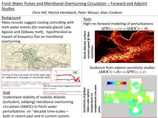
Example 1 : Thermal Comfort, convector PDE : Navier-Stokes + Buoyancy
Example 1 : Thermal Comfort , convector PDE : Navier-Stokes + Buoyancy
Durability of constructions Heat , Air & Moisture (HAM) transport
Example 2 Durability : 2D Moisture transport PDE : Coupled Heat & Moisture
Example 3 Durability : wind and rain around a building PDE : Navier-Stokes + k-eps + trajectories
Example 4 Durability: 3D Thermal construction PDE : Navier-Stokes + Buoyancy
Multi scale coupling Detail (scale 0.01 m) Whole Building (scale 10 m) Coupled [Abocad] [Abocad] Coupling? Global building model Local model
Problem Coupling • External • Multiple software programs • BPS Research of Hensen et al. • Internal • Single software: MatLab • BPS Research of Schijndel et al.
simulation environment: SimuLink • Coupling of models
HAMLab, whole building (global) • New Hybrid modeling approach • Both discrete and continuous • Discrete: climate related • Continuous: indoor air related • Accurate results for both time scales (hour & seconds) • Efficient calculation time
SimuLink using S-functions, Example (Heat Pump Model) 2/2 %t = time %u(1)=Tvin %u(2)=Fvin %u(3)=Tcin %u(4)=Fcin %u(5)=Ehp %u(6)=k [-] % %x(1)=Tvout %x(2)=Tcout function sys=mdlDerivatives( t, x, u) Tvm=(u(1)+x(1))/2; Tcm=(u(3)+x(2))/2; COP=u(6)*(273.15+Tcm)/(Tcm-Tvm); .. xdot(1)=(1/Cv)*(u(2)*cv*(u(1)-x(1))-(COP-1)*u(5)); xdot(2)=(1/Cc)*(u(4)*cc*(u(3)-x(2))+COP*u(5)); ..
Case study: energy roof systemComplete including Controllers 1/3
Case study: energy roof systemComplete including Controllers 2/3
Case study: energy roof systemComplete including Controllers 3/3
GOAL: preservation of the original paper fragments (Note: nearly 1 million visitors per year) HAMLab, HVAC & primary systems, exampleHVAC & Indoor air simulation of museum
HAMLab, HVAC & primary systems, exampleHVAC & Indoor air simulation of museum 100% of time out of limits!
HAMLab, HVAC & primary systems, exampleHVAC & Indoor air simulation of museum
HAMLab, HVAC & primary systems, exampleHVAC & Indoor air simulation of museum
HAMLab, HVAC & primary systems, exampleHVAC & Indoor air simulation of museum OK !
Airflow modeling, geometry and boundaries The boundary conditions are: At the left, right, top and bottom walls: u=0, v=0, T=0. At the inlet: u=1, v=0, T=1. At the outlet : Neuman conditions for u,v and T
Air temperature with low inlet velocity Re =50 , Gr =0
Air temperature with high inlet velocity Re =1000 , Gr =0
Air temperature with high inlet velocity & buoyancy Re =1000 , Gr =2.5e7
Validated result Simulation