Download
1 / 72
760 likes | 795 Views
J1939 Training. Agenda Basic Training: J1939 Vocabulary Basic Training: Monitoring Basic Training: Control Basic Training: Tools / Information Advanced: J1939 message breakdown Advanced: J1939 diagnostic messages Advanced: J1939 multiplexing. J1939 Training. Vocabulary:

E N D
J1939 Training • Agenda • Basic Training: J1939 Vocabulary • Basic Training: Monitoring • Basic Training: Control • Basic Training: Tools / Information • Advanced: J1939 message breakdown • Advanced: J1939 diagnostic messages • Advanced: J1939 multiplexing
J1939 Training • Vocabulary: • Datalink: Term used to describe how devices communicate with each other also referred to as a network. • Bit: One binary value. A “1” or “0” • Byte: 8 bits put together. Ex: “00000001” • Bit Field: Number of bits which are grouped together • CAN Data Frame: Series of ordered bit fields
J1939 Training • Vocabulary (cont.) • Cyclic Redundancy Check (CRC): Error control mechanism used to detect when a message was corrupted during transimission. • Data Field: 0-64 bit field in the CAN data frame which contains the actual data such as oil pressure or coolant temperature as defined in J1939/71 standard.
J1939 Training • Vocabulary (cont.) • Destination Address: Address of who is suppose to receive the message. (not included in all J1939 messages) • Global Address is 255 or FF hex • Device: Any physical component which listens to or sends information out on the J1939 datalink. • Electronic Control Unit: same as a device
J1939 Training • Vocabulary (cont.) • End of Frame: 7 bit field which marks the end of a CAN frame • Extended Frame: A CAN frame which contains a 29 bit identifier as defined in the CAN2.0B standard. • Note: J1939 allows both 11bit and 29 bit Identifers to coexist on the same network. • Frame: A series of data bits making up a complete message. The frame contains several bit fields
J1939 Frame End of Frame Bit Start of Frame Bit ACK Field Header # of bytes 8 bytes of actual data CRC Priority # PDU Format Source Address 4 bits representing numbers 0-15 typically 8 Actual data you are trying to send Used for Error Checking
J1939 Training • Vocabulary (cont.) • Message: One or more CAN data frames which transfer a complete piece of information to other devices on the datalink. • Multipacket Message: Messages which require multiple CAN data frames. These are handled by the “transport protocol”. • Protocol: A protocol is the “language” of how to communicate between devices.
J1939 Training • Vocabulary (cont.) • Parameter Group Number (PGN): a 24 bit identifier used to identify a message which contains a particular group of parameters. • Parameter Group: A collection of parameters that are conveyed in a J1939 message. • PDU1 Format: Format used when specifying a destination address
J1939 Training • Vocabulary (cont.) • PDU2 Format: Format used when broadcasting information. • Priority: The highest priority is zero. Lowest priority is seven. • Source Address: Address of who is sending the message on the datalink. • Start of Frame: Bit used to indicate the start of a CAN frame.
J1939 Training • Vocabulary (Cont.) • Suspect Parameter Number (SPN): The particular element which is having a problem. This is used in the fault codes to tell us which part is having a problem. (Sensor, ECM, etc..) • Failure Mode Identifer (FMI): Used to say how a particular SPN has failed.
OSI Network Model Layer Number 7 6 5 4 3 2 1 Application Application Presentation Presentation Session Session Transport Transport Network Network Data Link Data Link Physical Physical Physical Transmission Media
OSI Network Model • Physical Layer • Translates bits to waveforms required by electrical interface • Data Link Layer • Adds “header” and “trailer” to message for determining if errors occurred in message transmission, start and end of frame, etc... • Network Layer • Adds or looks at who sent the message and where the message going • Transport Layer • Breaks and reassembles large messages into smaller messages for sending over the network • Session Layer • Handles access rights … may not want everyone to see all data
OSI Network Model • Presentation Layer • Data encryption, data compression, etc... • Application Layer • Whatever is left over from other layers….
OSI Network Model • Most protocols do not specify each layer of the OSI model. J1939 does not specify each layer of the model. • Currently the following layers are given specific documents in the J1939 standardLayer 1 -- J1939/11 Layer 2 -- J1939/21 Layer 3 -- J1939/31 Layer 7 -- J1939/71 & /73
J1939 Training • What can I monitor? • What must I monitor to remove the indicator lights? • Where do I find out how to interpret the messages? • Example of reading oil pressure
J1939 Training All Module Information Request Only Data Broadcast Data
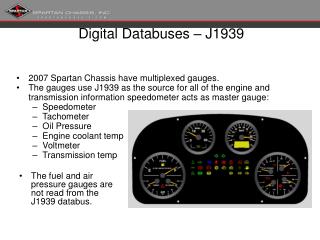
J1939 Training • What can I monitor? • Sensor parameters such as coolant temperature, oil pressure, etc… • Engine Fault Codes
J1939 Training • What must I monitor to remove the indicator lights? • All fault code SPNs (suspect parameter number and FMIs (failure mode indicator) must be displayed.
J1939 Training • Where do I find out how to interpret the messages? • Parameter data messages are found in the J1939/71 standard. Find the PGN first then look up the individual parameter definitions. • Fault Code (Diagnostic) messages are found in the J1939/73 standard. You will also need to use the wiring diagram, or AEB for the specific engine to understand what Cummins fault code goes with a SPN / FMI pair.
J1939 Control • What can the customer control? • Engine speed can be controlled via the J1939 datalink. • Fan Clutch
J1939 Training • High Speed datalinks • Reflections & Terminations • Topology • Troubleshooting
J1939 Training • Reflections & Terminations • Terminations are required to minimize reflections on the datalink (demo) • J1939/11 requires two 120ohm terminations for the datalink. • EA options for QSX/QSM only use one 120ohm termination due to the short length between the ECM and the service datalink connection. • ICAD Database has more detailed information
J1939 Training • Circuit block diagram • Most of our modules use the Intel 82527 Serial Communcations Controller ( CM500, CENSE, CM550, CM570, etc...) • Example circuits shown in J1939/11 specification Inside ECM Outside ECM Micro ( 68332 ) Serial Communications Controller ESD Protection Circuit CAN Transceiver
J1939 Topology Length of Backbone: .1 - 40m Length of Stub: 0 - 1m Maximum number of nodes: 30 Terminations : 120Ω Minimum Spacing: 0.1 m Note: Do not equally space the node connections on the backbone Stub 120Ώ 120Ώ Backbone
J1939 Addressing • Dynamic Addressing • Each ECM on the network takes on an address at startup. The specific address may be different from startup to startup. • Cummins does not support dynamic addressing; therefore, make sure each device on the datalink has a unique address.
J1939 Troubleshooting • Troubleshooting • First check the termination resistors. • Measure resistance between CAN_H and CAN_L. • Resistance should be approximately 60 ohms. If you have a small backbone like in the EA options, this may be closer to 120 ohms. • Check for frame errors • Using CANalyzer or other tool, monitor the J1939 datalink to see if any frame errors are recorded.
J1939 Troubleshooting • Troubleshooting (cont.) • Monitor broadcast parameters using CANalyzer • For multiplexed parameters, verify that the OEM / DOEM is sending the correct source address in the message. • Unplug other devices from the datalink so only the PC and ECM are on the network.
J1939 Tools • Tools • Protocol analyzer • Must have a protocol analyzer to develop a datalink interface. • Must have the J1939 standard unless customer already has good familiarity with CAN 2.0B protocol.
J1939 Tools • CANalyzer • In North America contact: Vector CANtech Inc. (248) 449-9290 Matt Palmer • Outside America contact: 49-711-80670-505 Lother Felbinger • Approximate Cost: Software: $2,700 Hardware: $1,185
J1939 Tools • Jpro • Cummins owned distributors: Software available through engineering tools (see intranet site: etools.ctg.cummins.com) Hardware available through Industrial Communication Technologies. • North America: call (978) 499 - 9271 • Outside North America: 49 89 46 1090 • Appoximate costs: $910 • Non Cummins owned distributors: Software is NOT available through engineering tools. Recommend CANalyzer • Jpro support from manufacturer ends 12/01.
J1939 Tools • Quick Check II available 4th Qtr 2001 • J1939 specification • Can be ordered online at www.sae.org for $495.00 USD for non-SAE members and $395.00 USD for SAE members.
J1939 Frame End of Frame Bit Start of Frame Bit ACK Field Header # of bytes 8 bytes of actual data CRC Priority # PDU Format Source Address 4 bits representing numbers 0-15 typically 8 Actual data you are trying to send Used for Error Checking
J1939 29 bit Identifier CAN Extended Frame Format S O F Identifier 11 bits S R R I D E Identifier Extension 18 bits R T R Priority PDU Format 6 bits (MSB) S R R I D E PF PDU Specific Destination Address, Group Ext, or Proprietary J1939 Frame Format Source Address S O F D P R R T R 2 1 6 5 4 4 3 8 7 3 2 1 8 7 6 5 3 2 1 8 7 5 4 3 2 6 1 J1939 Frame bit position 1 4 1 3 1 5 1 1 1 6 1 7 1 8 1 9 1 0 1 2 2 0 2 1 2 2 2 3 2 4 2 5 2 6 2 7 2 8 2 9 3 0 3 2 3 1 3 3 2 3 4 5 6 1 9 8 1 1 2 5 2 4 2 3 2 2 2 1 2 0 1 4 1 3 1 2 1 0 2 7 2 6 1 9 1 8 1 5 CAN 29 bit ID position 2 8 1 7 1 6 9 8 7 6 5 1 4 3 2 0
J1939 29 bit Identifier Header Breakdown (29 bits) 1 8 F E D F 0 2 1 1000 1111 1110 1101 1111 0000 0010 Data Page Reserved 3 bits Priority Number PDU Format (PF) PDU Specific (PS) Contains Destination Address if PF <239 Source Address
J1939 Data Message Interpretation • Looking at data messages on the CANalyzer.0.1360 1 18FEDF02x Rx d 8 7D E0 2E 7D FF FF FF FF time CAN Serial Input # Rx or TX # of Data Bytes 8 bytes of data represented in hexadecimal 29 bit header
J1939 Data Message Interpretation Example from J1939/71 Specification Section in specification which tells you how to interpret the actual data field
J1939 Data Message Interpretation On CANalyzer: 0.1000 1 0CF00300x Rx d 8 7D E0 2E 7D FF FF FF FF 0 C F 0 0 3 0 0 01100 1111 00000000 00110000 0000 Data Page Reserved 3 bits Priority Number PDU Format (PF) PDU Specific (PS) Contains Destination Address if PF <239 Source Address
J1939 Data Message Interpretation Conversion Formula: Accelerator Pedal Position % = Raw Counts * Resolution + offset Data Byte 2 which represents the accelerator pedal position Example: From CANalyzer: 0.1000 1 0CF00300x Rx d 8 7D E0 2E 7D FF FF FF FF Calculate Raw Counts First: Raw Counts = E0 hex = 1110 0000 binary = 224 decimal Note: You can use the Scientific calculator under Accessories in Win9X or Win NT to convert from hex to decimal. Accelerator Pedal Position % = 224 * .4 + 0 = 89.6%
J1939 Data Message Interpretation Example from J1939/71 Specification
J1939 Data Message Interpretation Conversion Formula: Engine Coolant Temperature = Raw Counts * Resolution + offset Data Byte 1 Example: From CANalyzer: 0.1000 1 0CFEEE00x Rx d 8 7D E0 2E 7D FF FF FF FF Calculate Raw Counts First: Raw Counts = 7D hex = 0111 1101 binary = 125 decimal Note: You can use the Scientific calculator under Accessories in Win9X or Win NT to convert from hex to decimal Engine Coolant Temperature = 125 * 1 - 40 = 85 deg C
J1939 Fault Code Interpretation • J1939 has several different messages which contain diagnostic (fault) code information. • DM1 - Active Fault Codes • DM2 - Inactive Fault Codes • DM3 - Clear Inactive Fault Codes • Typically customers will use the DM1 message to detect when a fault code has gone active.
J1939 Fault Code Interpretation • The DM1 message can be interpreted in one of two ways depending on which Cummins product you are working on. • HHP: QSK19 - QSKV60 use version 1 • All others: QSB - QSX use version 4 • Check byte 6 bit 8 to determine which SPN Conversion Method is to be used • byte 6 bit 8 = 0 = version 4 • byte 6 bit 8 = 1 = version 1
J1939 Fault Code Interpretation • DM1 message • 8 bytes of data are arranged as follows: Byte 1: bits 8-7 Malfunction Indicator Lamp Status bits 6-5 Red Stop Lamp Status bits 4-3 Amber Warning Lamp Status bits 2-1 Protect Lamp Status Each lamp takes two bits to indicate lamp state 00 - lamp is OFF 01 - lamp is ON
J1939 • Wait to Start Lamp is NOT found in the DM1 message! • PGN 65252 ( 00FEE4h ) Shutdown message byte 4 bits 2,1 • Broadcast once per second • other three lamps are part of the DM1 message
J1939 Fault Code Interpretation • DM1 byte 2 • All 8 bits are reserved for future SAE use. • OEMs should ignore all 8 bits in this byte. • DM1 byte 3 (for QSX, QSM, QSB,QSC, QSL9 only) • Contains the 8 lowest order bits for the SPN (Suspect Parameter Number). • Must combine this with byte 4 and part of byte 5 to get the 19 bit SPN number.
J1939 Fault Code Interpretation • DM1 byte 3 (for QSK, QSKV, QST only) • Contains the 8 highest order bits for the SPN (Suspect Parameter Number). • Must combine this with byte 4 and part of byte 5 to get the 19 bit SPN number.
J1939 Fault Code Interpretation • DM1 byte 4 (for QSX, QSM, QSB,QSC, QSL9 only) • Middle 8 bits of the SPN • DM1 byte 5 (for QSX, QSM, QSB,QSC, QSL9 only) • Contains the 3 most significant bits of the SPN, plus the FMI (Failure Mode Identifier) • Together the SPN and FMI map to the Cummins Fault Code.
J1939 Fault Code Interpretation • DM1 byte 4 (for QSK, QSKV, QST only) • Middle 8 bits of the SPN • DM1 byte 5 (for QSK, QSKV, QST only) • Contains the 3 least significant bits of the SPN, plus the FMI (Failure Mode Identifier) • Together the SPN and FMI map to the Cummins Fault Code.