Download
1 / 91
1.04k likes | 1.32k Views
授課教師: 楊宏智 教授. Manufacturing Engineering Technology Sheet-Metal Forming Processes and Equipment. 【 本著作除另有註明外,採取 創用 CC 「姓名標示-非商業性-相同方式分享」台灣 3.0 版 授權釋出 】. 【 本著作除另有註明外,採取 創用 CC 「姓名標示-非商業性-相同方式分享」台灣 3.0 版 授權釋出 】. 【 本著作除另有註明外,採取 創用 CC 「姓名標示-非商業性-相同方式分享」台灣 3.0 版 授權釋出 】. 楊宏智(台大機械系教授).

E N D
授課教師:楊宏智教授 Manufacturing Engineering Technology Sheet-Metal Forming Processes and Equipment 【本著作除另有註明外,採取創用CC「姓名標示-非商業性-相同方式分享」台灣3.0版授權釋出】 【本著作除另有註明外,採取創用CC「姓名標示-非商業性-相同方式分享」台灣3.0版授權釋出】 【本著作除另有註明外,採取創用CC「姓名標示-非商業性-相同方式分享」台灣3.0版授權釋出】
楊宏智(台大機械系教授) Manufacturing Engineering Technology機械製造
Chapter Outline Introduction Shearing Sheet-metal Characteristics and Formability Formability Tests for Sheet Metals Bending Sheets, Plates, and Tubes Miscellaneous Bending and Related Operations Deep Drawing Rubber Forming and Hydroforming Spinning Superplastic Forming Specialized Forming Processes Manufacturing of Metal Honeycomb Structures Design Considerations in Sheet-metal Forming Equipment for Sheetmetal Forming Economics of Sheetforming Operations
Introduction Products made of sheet metals are common Pressworking or press forming is used for general sheet-forming operations, as they are performed on presses using a set of dies
Introduction A sheet-metal part produced in presses is called a stamping Low-carbon steel has low cost and good strength and formability characteristics Manufacturing processes involving sheet metal are performed at room temperature
Sheet Metalworking Defined Cutting and forming operations performed on relatively thin sheets of metal Thickness of sheet metal = 0.4 mm (1/64 in) to 6 mm (1/4 in) Thickness of plate stock > 6 mm Operations usually performed as cold working
Sheet and Plate Metal Products Sheet and plate metal parts for consumer and industrial products such as Automobiles and trucks Airplanes Railway cars and locomotives Farm and construction equipment Small and large appliances Office furniture Computers and office equipment
Advantages of Sheet Metal Parts High strength Good dimensional accuracy Good surface finish Relatively low cost Economical mass production for large quantities
Sheet Metalworking Terminology Punch-and-Die - tooling to perform cutting, bending, and drawing Stamping press - machine tool that performs most sheet metal operations Stampings - sheet metal products
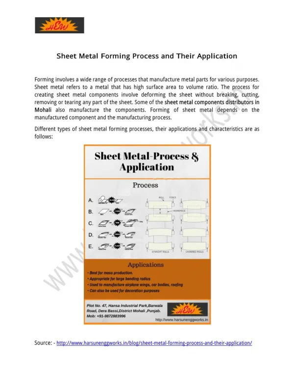
Three Basic Types of Sheet Metal Processes 1.Cutting (Shearing) Shearing to separate large sheets Blanking to cut part perimeters out of sheet metal Punching to make holes in sheet metal 2.Bending Straining sheet around a straight axis 3.Drawing Forming of sheet into convex or concave shapes
Sheet Metal Cutting (Shearing) (1) Just before punch contacts work; (2) punch pushes into work, causing plastic deformation; (3) punch penetrates into work causing a smooth cut surface; and (4) fracture is initiated at opposing cutting edges to separate the sheet
Shearing Before a sheet-metal part is made, a blank is removed from a large sheet by shearing The edges are not smooth and perpendicular to the plane of the sheet
Punch and Die Sizes Die size determines blank size Db Punch size determines hole size Dh c = clearance
Shearing Processing parameters in shearing are The shape of the punch and die The speed of punching Lubrication The clearance, c, between the punch and the die When clearance increases, the zone of deformation becomes larger and the sheared edge becomes rougher Extent of the deformation zone depends on the punch speed Height, shape, and size of the burr affect forming operations
Clearance in Sheet Metal Cutting Distance between punch cutting edge and die cutting edge Typical values range between 4% and 8% of stock thickness If too small, fracture lines pass each other, causing double burnishing and larger force If too large, metal is pinched between cutting edges and excessive burr results
Clearance in Sheet Metal Cutting Recommended clearance is calculated by: c = at where c = clearance; a = allowance; and t = stock thickness Allowance a is determined according to type of metal
Sheet Metal Groups Allowances Metal group a 1100S and 5052S aluminum alloys, all tempers 0.045 2024ST and 6061ST aluminum alloys; brass, 0.060 soft cold rolled steel, soft stainless steel Cold rolled steel, half hard; stainless steel, 0.075 half hard and full hard
Shearing Clearance Clearance control determine quality of its sheared edges which influence formability of the sheared part Appropriate clearance depends on: 1. Type of material and temper 2. Thickness and size of the blank 3. Proximity to the edges of other sheared edges When sheared edge is rough it can be subjected to a process called shaving
Shearing: Characteristics and Type of Shearing Dies Punch and Die Shape Punch force increases rapidly during shearing Location of sheared regions can be controlled by beveling the punch and die surfaces
Shearing Punch Force Maximum punch force, F, can be estimated from Friction between the punch and the workpiece can increase punch force T = sheet thicknessL = total length sheared UTS = ultimate tensile strength of the material
Shearing EXAMPLE 16.1 Calculation of Punch Force Estimate the force required for punching a 25-mm diameter hole through a 3.2-mm thick annealed titanium- alloy Ti-6Al-4V sheet at room temperature. Solution UTS for this alloy is 1000 MPa, thus
Blanking and Punching Blanking - sheet metal cutting to separate piece (called a blank) from surrounding stock Punching - similar to blanking except cut piece is scrap, called a slug
Shearing: Shearing Operations Punching is where the sheared slug is scrap Blanking is where the slug is the part to be used and the rest is scrap Die Cutting Shearing operation consists of: Perforating: punching holes in a sheet Parting: shearing sheet into pieces Notching: removing pieces from the edges Lancing: leaving a tab without removing any material
Shearing: Fine Blanking smaller clearance used pressure pad w/ v-shaped stringer locks the sheet metal movement of punch, pressure pad, cushion are controlled by triple-action hydraulic presses
Shearing Operations: Slitting Shearing operations are through a pair of circular blades, follow either a straight line, a circular path, or a curved path
Shearing Operations: Nibbling A contour is cut by a series of overlapping slits or notches Simple tools can be used to produce complex shape
Shearing: Tailor-welded Blanks Laser-beam butt welding involves two or more pieces of sheet metal with different shapes and thicknesses The strips are welded to obtain a locally thicker sheet and then coiled The welded assembly is then formed into a final shape. Resulting in: Reduction in scrap Elimination of the need for subsequent spot welding Better control of dimensions Improved productivity
Shearing: Tailor-welded Blanks EXAMPLE 16.2 Tailor-welded Sheet Metal for Automotive Applications Production of an outer side panel of a car body is by laser butt welding and stamping
Shearing: Tailor-welded Blanks EXAMPLE 16.2 Tailor-welded Sheet Metal for Automotive Applications Some of the examples of laser butt-welded and stamped automotive-body components.
Characteristics and Type of Shearing Dies Transfer Dies Sheet metal undergoes different operations arranged along a straight line or a circular path Tool and Die Materials Tool and die materials for shearing are tool steels and carbides Lubrication is needed for reducing tool and die wear, and improving edge quality
Characteristics and Type of Shearing Dies Progressive Dies a different operation is performed at the same station with each stroke of a series of punches
Characteristics and Type of Shearing Dies For high product production rates The part shown below is the small round piece that supports the plastic tip in spray cans
Characteristics and Type of Shearing Dies Compound Dies Operations on the same sheet may be performed in one stroke with a compound die Limited to simple shapes due to: Process is slow Complex dies is more expensive
Shearing: Miscellaneous Methods of Cutting Sheet Metal Other methods of cutting sheets Laser-beam cutting Water-jet cutting Cutting with a band saw Friction sawing Flame cutting
Sheet-metal Characteristics and Formability Yield-point elongation having both upper and lower yield points. This behaviour results in Luder’s bands Typically observed with mild-steel sheets Results in depressions on the sheet surface Can be eliminated by temple rolling (but sheet must be formed within a certain time after rolling)
Sheet-metal Characteristics and Formability Grain Size Affects mechanical properties and surface appearance Smaller the grain size, stronger is the metal Dent Resistance of Sheet Metals Dents caused by dynamic forces from moving objects that hit the sheet metal Dynamic yield stress, instead of static yield stress, should be the significant strength parameter
Formability Tests for Sheet Metals Sheet-metal formability is the ability of the sheet metal to undergo the desired shape change without failure Sheet metals may undergo 2 basic modes of deformation: (1) stretching and (2) drawing Cupping Tests In the Erichsen test, the sheet specimen is clamped and round punch is forced into the sheet until a crack appears The punch depth is a measure of formability of the sheet Easy to perform, but does not simulate exact conditions of actual forming, and not reliable for complex parts.
Formability Tests for Sheet Metals Forming-limit Diagrams To develop a forming-limit diagram, the major and minor engineering strains are obtained Major axis of the ellipse represents the major direction and magnitude of stretching Major strain is the engineering strain and is always positive Minor strain can be positive or negative Curves represent the boundaries between failure and safe zones
Formability Tests for Sheet Metals Forming-limit Diagrams Forming-limit diagrams is to determine the formability of sheet metals
Forming-Limit Diagram (FLD) Blank stretched over a punch, deformation observed and measured in the region where failure has occurred The curves represent the boundaries between failure and safe zones Different mat'ls have different FLDs, and the higher the curve, the better is the formability Compressive minor strain is associated with a higher major strain than a tensile minor strain of the same magnitude The effect of sheet-metal thickness is to raise the curves Friction, lubrication at punch/sheet-metal interface, and surface scratches, are important factors
Bending Sheets Bending is a common industrial forming operation Bending imparts stiffness to the part by increasing its moment of inertia Outer fibers are in tension, while the inner in compression Poisson effect cause the width to be smaller in the outer region and larger in the inner region , Plates, and Tubes
Bending Sheets, Plates, and Tubes Approximate bend allowance is For ideal case, k = 0.5, Minimum Bend Radius Engineering strain during bending is Minimum bend radius, R, is
Bending Sheets, Plates, and Tubes Minimum Bend Radius Increase the bendability by increase their tensile reduction of area Bendability also depends on the edge condition of the sheet Improve resistance to edge cracking by removing the cold-worked regions Cold rolling results in anisotropy by preferred orientation or mechanical fibering
Bending Sheets, Plates, and Tubes Springback Plastic deformation is followed by elastic recovery when the load is removed, called springback Springback can be calculated by
Bending Sheets, Plates, and Tubes Compensation for Springback Springback is compensated for by overbending the part One method is stretchbending where the part is subjected to tension while being bent Bending Force Excluding friction, the maximum bending force, P, is For a V-die, it is modified to
Miscellaneous Bending Operations Examples of various bending operations Roll Bending Plates are bent using a set of rolls. Curvatures can be obtained by adjusting the distance between the three rolls
V-Bending and Edge Bending V-Bending: Low production Performed on a press brake V-dies are simple and inexpensive Edge-Bending: High production Pressure pad required Dies are more complicated and costly
Miscellaneous Bending and Related Operations Beading Periphery of the sheet metal is bent into the cavity of a die The bead imparts stiffness to the part by increasing the moment of inertia of that section
Miscellaneous Bending and Related Operations Flanging In shrink flanging, the flange is subjected to compressive hoop stresses and cause the flange periphery to wrinkle
Bending Operations most common forming operation paper clip, file cabinet etc