Download
1 / 32
330 likes | 353 Views
SIGNAL FLOW GRAPH. Outline. Introduction to Signal Flow Graphs Definitions Terminologies Mason’s Gain Formula Examples Signal Flow Graph from Block Diagrams Examples. Signal Flow Graph (SFG). Alternative method to block diagram representation, developed by Samuel Jefferson Mason.

E N D
Outline • Introduction to Signal Flow Graphs • Definitions • Terminologies • Mason’s Gain Formula • Examples • Signal Flow Graph from Block Diagrams • Examples
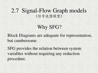
Signal Flow Graph (SFG) Alternative method to block diagram representation, developed by Samuel Jefferson Mason. Block diagram are adequate for representation but cumbersome. A signal-flow graph provides the relation between system variables without requiring any reduction procedures.
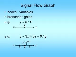
Fundamentals of Signal Flow Graphs Consider a simple equation below and draw its signal flow graph: The signal flow graph of the equation is shown below;
Important terminology : Branch • Dummy Nodes:- A branch having one can be added at i/p as well as o/p. • Branches :- line joining two nodes is called branch. Dummy Nodes
f c x0 x4 x1 x3 x2 g a d h b e Input & output node Input node • Input node:- It is node that has only outgoing branches. • Output node:- It is a node that has incoming branches. Out put node
Forward path:- Forward path Any path from i/p node to o/p node.
Loop :- A closed path from a node to the same node is called loop.
Self loop:- • A feedback loop that contains of only one node is called self loop. Self loop
Loop gain:- Loop gain = A32 A23 The product of all the gains forming a loop
Path & path gain Path:- A path is a traversal of connected branches in the direction of branch arrow. Path gain:- The product of all branch gains while going through the forward path it is called as path gain.
Feedback path or loop :- it is a path to o/p node to i/p node.
Touching loops:- when the loops are having the common node that the loops are called touching loops.
Non touching loops:- • when the loops are not having any common node between them that are called as non- touching loops.
Chain Node :- Chain node it is a node that has incoming as well as outgoing branches.
Mason’s Rule (Mason, 1953) The block diagram reduction technique requires successive application of fundamental relationships in order to arrive at the system transfer function. On the other hand, Mason’s rule for reducing a signal-flow graph to a single transfer function requires the application of one formula.
Mason’s Rule :- • The transfer function, C(s)/R(s),of a system represented by a signal-flow graph is; • Where • n = number of forward paths. • Pi = the i th forward-path gain. • ∆ = Determinant of the system • ∆i = Determinant of the ith forward path
∆ is called the signal flow graph determinant or characteristic function. Since ∆=0 is the system characteristic equation. ∆ = 1- (sum of all individual loop gains) + (sum of the products of the gains of all possible two loops that do not touch each other) – (sum of the products of the gains of all possible three loops that do not touch each other) + … and so forth with sums of higher number of non-touching loop gains ∆i = value of Δ for the part of the block diagram that does not touch the i-th forward path (Δi = 1 if there are no non-touching loops to the i-th path.)
Example1: Apply Mason’s Rule to calculate the transfer function of the system represented by following Signal Flow Graph Therefore, There are three feedback loops Continue……
There are no non-touching loops, therefore ∆ = 1- (sum of all individual loop gains) Continue……
Eliminate forward path-2 Eliminate forward path-1 ∆1 = 1- (sum of all individual loop gains)+... ∆2 = 1- (sum of all individual loop gains)+... ∆1 = 1 ∆2 = 1 Continue……
H1 C(s) R(s) X1 - E(s) X3 G1 G3 G4 G2 - X2 - H2 H3 -H1 X2 R(s) X1 X3 1 C(s) E(s) G1 G2 G4 1 G3 -H2 -H3 From Block Diagram to Signal-Flow Graph Models Example2 Continue……
-H1 X2 R(s) X1 X3 1 C(s) E(s) G1 G2 G4 1 G3 -H2 -H3
Example 4 Continue……