Download
1 / 19
220 likes | 342 Views
Microwave Experiments. Fred, Geoff, Lise,and Phil. Intensity vs. Angle. S. Probe. Basic Optics. Reflection Angles Standing Waves Speed of light: c= ln =(freq*(x/nodes)*2) 10.5 ± .1 Ghz -> 3.01E8±.03E8 m/s (typical). x. q I. q R. S. Probe: Count Nodes in x. S. M. Intensity.

E N D
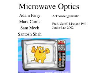
Microwave Experiments Fred, Geoff, Lise,and Phil
Intensity vs. Angle S Probe
Basic Optics • Reflection • Angles • Standing Waves • Speed of light: c=ln =(freq*(x/nodes)*2) • 10.5 ± .1 Ghz -> 3.01E8±.03E8 m/s (typical) x qI qR S Probe: Count Nodes in x S M
Intensity • Point Source: I~1/r2 • Our Source: I~1/r S M r
Refraction Through a Prism • Use prism • See handout for experiment diagram • Measure the angle of maximum intensity • Using this angle and Snell’s Law, calculate the index of refraction of the Prism • n = 1.46
S Received Signal Polarization Receiver Polarization q Source Polarization • Polarization: Direction of E-field • Our source and receiver are polarized • Only projection of E onto polarization of receiver is detected: Ereceived~ cos (q) • Intensity ~ cos 2(q) M
Interference z q f d q • Path Difference • Wave is f(kx-wt) • Implies Phase Diff. • D=kd = (2p/l) f (z/d)=f sin(q) • Effect of D • E~sin(kx-wt-.5 kd) + sin(kx-wt+.5 kd) = 2sin(kx-wt) cos(.5 kd) • I~E2 • I~ cos2(.5 kd) = cos2(.5 k f sin(q)) d>>f -> sin(q)->tan(q) So d = f (z/d) d
Double Slit Interference • Diffraction Effects • Intensity from each source varies as sin2(a)/a2, where a=.5 k w sin(q), w=slit width • So I~ sin2(.5k sin(q) w) cos2(.5k sin(q) f) /(.5 k sin(q) w)2 • Prediction • Black: Diffraction • Blue: Diff. + Interference I f = 2 w q
S M Mirror Extension Double Slit Results • Results • Envelope and Interference • Limit of Resolution of Angle?
S M Single Slit Diffraction • Used various slit widths and measured intensity verses angle • sin(q) = nl/a Mirror Extension a
Lloyd’s Mirror S M • Premise • Two ways to reach detector • Off of mirror or straight line • Path difference implies interference • 2*(Distance Between Maxima)=l • Results • Wavelength: • 2.5 ± .7 cm • c=2.6E8 m/s ± .3E8 m/s
Fabry-Perot Interferometer • Changing the interference pattern between two partial reflectors allows us to measure the wavelength. • See handout for experiment diagram • (d2 – d1)/M = l • We measured l = 2.62 ± 0.1 and l = 3 ± 0.1
Michelson Interferometer • Setup • Beam Splitter • Path Difference->Interference • Results • Wavelength= S M
Fiber Optics • Using tube filled with styrene pellets, we noticed higher transmission levels • Although very sensitive to positioning, the signal was rather constant with different curvatures
Bragg Diffraction • Bragg’s law give us a way to measure distances between crystal planes • d sin q = n l/2 where d is the distance between crystal planes http://www.physics.sfsu.edu/~bland/courses/490/labs/d2/braggthy.html
M Frustrated Total Internal Reflection 2 1 S • Setup • Is there any transmission to 2?
Lenses S