Download
1 / 43
520 likes | 698 Views
V. Broadband Antennas. Broadband Antenna. Bandwidth Broadband Non-resonant type -traveling wave antenna, vee, rhombic antenna -helical, log-periodic antenna -conical antenna. Traveling wave antenna. For short-wave band: 2~30MHz. Traveling wave antenna.

E N D
Broadband Antenna • Bandwidth • Broadband • Non-resonant type • -traveling wave antenna, vee, rhombic antenna • -helical, log-periodic antenna • -conical antenna
Traveling wave antenna For short-wave band: 2~30MHz
Traveling wave antenna Traveling wave antenna in free space Unnormalized pattern factor Pattern with n forward lobe Element factor
Traveling wave antenna Traveling wave VEE antenna in free space
Traveling wave antenna Rhombic antenna in free space
Traveling wave antenna Ground effect (perfect ground)
Traveling wave antenna Beverage antenna: Traveling wave ant. above the earth with imperfect conducting properties Tangential Electric field on earth is not zero =>1.inducing a current on the antenna conductor. 2.due to unbalanced operation, can radiate the field. Loss and standing wave
Beverage antenna Loss:radiation and dissipation in earth Reflection from load end
Helical antenna Mode of Helix
Normal mode Helix Direction of maximum directivity: Normal to the axis of Helix Normal mode
Normal mode Helix For circular polarization, Normal mode helix is usually operated as linearly polarized
Normal mode Helix Resonant stub helix antenna on ground plane
Axial mode Helix Hansen-Woodyard
Axial mode Helix Useful axial mode helix design
With tapered helix, bandwidth and axial ratio are improved uniform end taper continous taper nonuniform Polarization LHCP RHCP
Biconical Antenna Analysis Spherical TEM wave Infinite bicone
Finite biconical Antenna Non-ideal open: non TEM higher mode
conical monopole antenna monopole bandwidth
Discone antenna disc+cone
Sleeve antenna(monopole) Virtual feed
Frequency independent antennas • Bandwidth over 10:1 -pattern, impedance, polarization, phase center.. • Frequency-independent antennas are designed to minimize finite length and maximize angular dependence. Helix - geometry of angular dependent • Self-complimentary structure • Thick metal biconical, bow-tie • Self-scaling property: most radiation takes place from the active region
Self complimentary Self complimentary: A antenna and its complimentary are identical complimentary Frequency independent
Equiangular antenna antenna of geometry enlarged antenna For enlarged surface coincides with original one
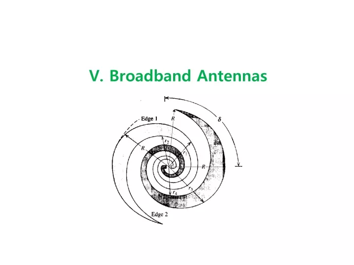
Spiral antennas truncated Equiangular spiral Expansion ratio
Equiangular spiral Frequency range(bandwidth) Antenna impedance Finite thickness Coaxial feed Pattern HPBW Polarization:circular as helix
Archimedean spiral 1.feed to active region ->act as transmission line 2. active region ->radiation takes place 3. Beyond the active region ->currents can be neglected active region: portion of the antenna that is one wavelength in circumference Circular polarization
Cavity-backed Archimedean spiral For unidirectional beam
Conical equiangular spiral Main beam
Log-periodic Antennas Logarithmically periodic structure The electrical properties vary periodically with the logarithm of the operating frequency Scaling of antenna dimension Scaling of operating frequency Spiral antenna: continuously scaled structure scaling->rotation of the structure
Log-periodic Self complementary Active region: tooth with length of quarter wavelength
Main beam direction: normal to the plane of antenna(bidirection) Polarization: linear polarization normal to that of bow-tie(without teeth) Operating band: determined by the length of the largest and the smallest tooth
Log-periodic toothed wedge(unidirectional) Log-periodic toothed trapezoid Log-periodic wire Trapezoid zig-zag Log-periodic wire Trapezoid(circular pol.)
Log-periodic dipole array(LPDA) Series-fed array of log periodically scaled parallel wire dipoles Main beam
Log-periodic dipole array(LPDA) Log-periodic