Download
1 / 18
260 likes | 871 Views
Programmable Peripheral Interface: 8255. Prepared By: Prof. M. B. Salunke SITS, Narhe, Pune - 41. E-mail: msalunke@gmail.com Web: www.salunke.webs.com. Features of 8255. 24 Programmable I/O Pins, Widely used programmable parallel I/O device,

E N D
Programmable Peripheral Interface: 8255 Prepared By:Prof. M. B. SalunkeSITS, Narhe, Pune - 41. E-mail: msalunke@gmail.com Web: www.salunke.webs.com
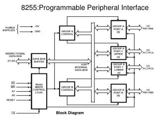
Features of 8255 • 24 Programmable I/O Pins, • Widely used programmable parallel I/O device, • Interfaces peripheral components to the system bus through its three 8-bit ports, • Fully TTL compatible, • Direct Bit Set/Reset Capability, • Enhanced Control Word Read Capability, • High Speed, No “Wait State” Operation with 5MHz and 8MHz 80C86 and 80C88
Operational Description • Mode Selection There are three basic modes of operation that can be selected by the system software: • Mode 0 - Basic Input/Output • Mode 1 - Strobed Input/Output • Mode 2 - Bi-directional Bus
Operating Modes • Mode 0 (Basic Input/Output) Basic Functional Definitions: • Two 8-bit ports and two 4-bit ports • Any Port can be input or output • Outputs are latched • Input are not latched • 16 different Input/Output configurations possible
Operating Modes • Mode 1 - (Strobed Input/Output). Basic Function Definitions: • Two Groups (Group A and Group B) • Each group contains one 8-bit port and one 4-bit control/data port • The 8-bit data port can be either input or output. Both inputs and outputs are latched. • The 4-bit port is used for control and status of the 8-bit port.
STB# (Strobe Input) • IBF (Input Buffer • Full F/F) • INTR (Interrupt • Request) • INTE A • Controlled by bit • set/reset of PC4. • INTE B • Controlled by bit • set/reset of PC2.
OBF# (Output Buffer • Full F/F) • ACK# - (Acknowledge • Input). • INTR (Interrupt • Request) • INTE A • Controlled by bit • set/reset of PC6. • INTE B • Controlled by bit • set/reset of PC2.
Operating Modes • Mode 2 (Strobed Bi-Directional Bus I/O) Basic Functional Definitions: • Used in Group A only • One 8-bit, bi-directional bus Port (Port A) and a 5-bit control Port (Port C) • Both inputs and outputs are latched • The 5-bit control port (Port C) is used for control and status for the 8-bit, bi-directional bus port (Port A)
OBF# (Output Buffer • Full F/F) • ACK# - (Acknowledge • Input). • IBF (Input Buffer • Full F/F) • STB# (Strobe Input) • INTR (Interrupt • Request) • INTE 1 • Controlled by bit • set/reset of PC6. • INTE 2 • Controlled by bit • set/reset of PC4.