Download
1 / 25
270 likes | 497 Views
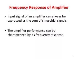
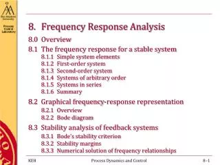
ECE 342 8. Frequency Response of Amplifiers. Jose E. Schutt-Aine Electrical & Computer Engineering University of Illinois jschutt@emlab.uiuc.edu. Low-Pass Circuit. In frequency domain:. Low-Pass Circuit. At very high frequencies, the single time constant (STC) transfer function goes as.

E N D
ECE 342 8. Frequency Response of Amplifiers Jose E. Schutt-Aine Electrical & Computer Engineering University of Illinois jschutt@emlab.uiuc.edu
Low-Pass Circuit In frequency domain:
Low-Pass Circuit At very high frequencies, the single time constant (STC) transfer function goes as At high frequencies, slope of curve is –20 dB
Octave & Decade If f2 = 2f1, then f2 is one octave above f1 If f2 = 10f1, then f2is one decade above f1 2 GHz is one octave above 1 GHz 10 GHz is one decade above 1 GHz
Frequency Response 3-dB points are points where the magnitude is divided by 21/2 (power is halved) |1+j|= 21/2 AdB= 20log1.414 = 3 dB Amplifier has intrinsic gain Ao Low-pass characteristics is: High-pass characteristics is: Overall gain A(f) is
Octave & Decade Overall gain A(f) is
Model for general Amplifying Element Cc1 and Cc2are coupling capacitors (large) mF Cin and Cout are parasitic capacitors (small) pF
Midband Frequencies • Coupling capacitors are short circuits • Parasitic capacitors are open circuits
Low Frequency Model • Coupling capacitors are present • Parasitic capacitors are open circuits
Example Rout = 3 kW, Rg=200 W, Rin=12 kW, RL=10 kW Cc1=5 mF and Cc2=1 mF
High Frequency Model • Assume coupling capacitors are short • Account for parasitic capacitors Potential Thevenin equivalent for input as seen by Cin
High Frequency Overall gain is: or
Important Remarks • An arbitrary network’s transfer function can be described in terms of its s-domain representation • s is a complex number s = s + jw • The impedance (or admittance) or networks can be described in the s domain
Transfer Function Representation The coefficients a and b are real and the order m of the numerator is smaller than or equal to the order n of the denominator A stable system is one that does not generate signal on its own. For a stable network, the roots of the denominator should have negative real parts
Transfer Function Representation In general, the transfer function of an amplifier can be expressed as Z1, Z2,…Zmare the zeros of the transfer function P1, P2,…Pmare the poles of the transfer function • s is a complex number s = s + jw
3dB Frequency Determination • Designer is interested in midband operation • However needs to know upper 3-dB frequency • In many cases some conditions are met: • Zeros are infinity or at very high frequencies • One of the poles (wP1) is at much lower frequency than other poles (dominant pole) • If the conditions are met then FH(s) can be approximated by:
3dB Frequency Determination If the lowest frequency pole is at least 4 times away from the nearest pole or zero, it is a dominant pole If there is no dominant pole, the 3-dB frequency wH can be approximated by:
Open-Circuit Time Constants The coefficients a and b are related to the frequencies of the zeros and poles respectively. b1 can be obtained by summing the individual time constants of the circuit using the open-circuit time constant method
Open-Circuit Time Constant Method • The time constant of each capacitor in the circuit is evaluated. It is the product of the capacitance and the resistance seen across its terminals with: • All other internal capacitors open circuited • All independent voltage sources short circuited • All independent current sources opened • The value of b1 is computed by summing the individual time constants
Open-Circuit Time Constant Method • An approximation can be made by using the value of b1 to determine the 3dB upper frequency point wH • If the zeros are not dominant and if one of the poles P1 is dominant, then Assuming that the 3-dB frequency will be approximately equal to wP1