Download
1 / 47
470 likes | 568 Views
Energy Consumption Evaluation of an Adaptive Extensible Processor. Hamid Noori, Farhad Mehdipour, Maziar Goudarzi, Seiichiro Yamaguchi, Koji Inoue , and Kazuaki Murakami Kyushu University December 2007. Outline. Introduction General Overview of the Proposed Approach

E N D
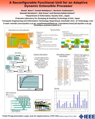
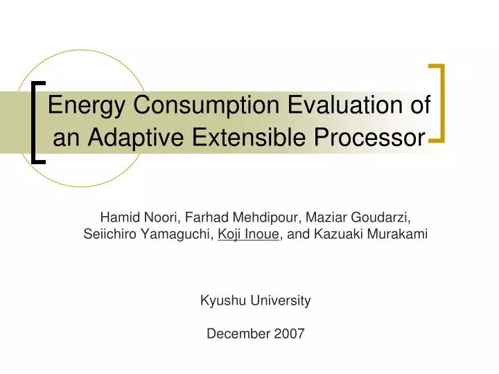
Energy Consumption Evaluation of an Adaptive Extensible Processor Hamid Noori, Farhad Mehdipour, Maziar Goudarzi, Seiichiro Yamaguchi, Koji Inoue, and Kazuaki Murakami Kyushu University December 2007
Outline • Introduction • General Overview of the Proposed Approach • Multi-Exits Custom Instructions • Energy Consumption Evaluation • Evaluation Results • Conclusions and Future Work
Outline • Introduction • General Overview of the Proposed Approach • Multi-Exits Custom Instructions • Energy Consumption Evaluation • Evaluation Results • Conclusions and Future Work
Introduction (1/2) • Embedded processors have to achieve • Lowcost • High-performance • Low-power or low-energy consumption • Key point • How can processors adapt to target applications? • Solution: ASIP w/ Re-configurability • Application specific ISA • Provide custom instructions (CIs) • Implement re-configurable FUs
Introduction (2/2) • Adaptive, extensible processor [DATE’07] • Has a coarse-grain re-configurable functional unit • Supports efficient “Multi-Exits CIs” • Achieves high-performance and low-cost • Question • How about energy efficiency? • Results: Energy saving • v.s. base processor: 42% • v.s. single basic-block based CIs: 15%
Outline • Introduction • General Overview of the Proposed Approach • Multi-Exits Custom Instructions • Energy Consumption Evaluation • Evaluation Results • Conclusions and Future Work
ADaptive EXtensible processOR(ADEXOR) • Generating and adding CIs AFTER chip fab. Utilization phase Instruction Dispatcher Config Mem + & x LD/ST CFU1 CRFU Register File
Execution Overview of ADEXOR 400680 subiu $25,$25,1 400688 lbu $13,0($7) 400690 lbu $2,0($4) 400698 sll $2,$2,0x18 4006a0 sra $14,$2,0x18 4006a8 addiu $4,$4,1 4006b0 srl $8,$2,0x1c 4006b8 sll $2,$8,0x2 4006c0 addu $2,$2,$25 4006c8 bgez $10,4006f0 4006d0 xori $13,$13,1 4006d8 addu $10,$10,$2 400680 subiu $25,$25,1 400698 sll $2,$2,0x18 4006a0 sra $14,$2,0x18 400688 lbu $13,0($7) 4006e0 bgez $10,4006f0 . . . . Register File Indexed by mtc1 RFU or sequencer Configuration Memory ID/EXE Reg ID/EXE Reg CRFU ALU MUX Counter Triggered by mtc1 or sequencer EXE/MEM Reg GPP Augmented HW GPP: General Purpose Processor RFU: Reconfigurable Functional Unit Hot Basic Block
Outline • Introduction • General Overview of the Proposed Approach • Multi-Exits Custom Instructions • Evaluation Results • Conclusions and Future Work
Why Multi-Exits Custom Instructions (MECIs)? Conventional BB-base CI Generation (Single-Enter Single-Exit) #Required nodes: 4 BB1 BB3 BB4 adpcm BB2 beq 0 7 10 1 2 3 bgez 5 8 9 bne 11 12 95% 5% 30 ……………. bne 20 19 17 15 18 16 14 BB6 BB5 Assume 20 nodes can be included in one CI in maximum
Why Multi-Exits Custom Instructions (MECIs)? BB-base CI w/ Conditional Execution Support (Single-Enter Single-Exit) #Required nodes: 22 (can not map) BB1 BB3 BB4 adpcm BB2 beq 0 7 10 1 2 3 bgez 5 8 9 bne 11 12 95% 5% 30 ……………. bne 20 19 17 15 18 16 14 BB6 BB5 Assume 20 nodes can be included in one CI in maximum
Why Multi-Exits Custom Instructions (MECIs)? Multiple-Exits Custom Instruction Conditional Execution + Hot-Path Selection #Required nodes: 17 BB1 BB3 BB4 adpcm BB2 beq 0 7 10 1 2 3 bgez 5 8 9 bne 11 12 95% 5% Exit 30 ……………. bne 20 19 17 15 18 16 14 Exit BB6 BB5 Assume 20 nodes can be included in one CI in maximum
Main features of MECIs • Fixed point operations √ • Multiply x • Divide x • Control flow √ • Memory instructions x
Custom Instruction Invocation • How to change the execution sequence and run custom instructions on the CRFU? • Software (mtc1-like instruction) method • Hardware (table look-up) method
0 inst. # address inst. operands (dest, src1, src2) inst. # address inst. operands (dest, src1, src2) 1 400410 R23 R2 lw 100 0 400410 addu R13 R0 R0 1 400418 R23 R2 lw 100 2 400420 addiu R4 R4 2 2 400420 addiu R4 R4 2 3 400428 subu R3 R2 R11 3 400428 subu R3 R2 R11 4 400430 bgez 400440 R3 4 400430 bgez 400440 R3 5 400438 addiu R13 R0 8 5 400438 addiu R13 R0 8 6 400440 beq 400468 R13 6 400440 beq 400468 R13 7 400448 subu R3 R0 R3 7 400448 subu R3 R0 R3 8 400450 addu R10 R0 R0 8 400450 addu R10 R0 R0 10 400458 slt R2 R3 R9 9 400458 lw R8 R9 0x3 9 400460 lw R8 R9 0x3 10 400460 slt R2 R3 R9 11 400468 12 400470 13 400478 bne 4004a8 R2 13 400478 bne 4004a8 R2 14 400480 addiu R10 14 400480 addiu R10 R0 4 15 400488 subu R3 R3 R9 16 400490 addu R8 R8 R9 17 400498 sra R9 R9 0x1 18 4004a0 slt R2 R3 R9 19 4004a8 ori R10 R10 2 20 4004b0 subu R3 R3 R9 21 4004b8 bne 400410 R2 22 4004c0 slt R2 R3 R9 Software method exit4 mtc1 beq 7 2 3 bgez 5 8 10 bne 11 12 exit3 exit1 bne 20 19 Instruction scheduling exit2 0 400418 addu R13 R0 R0 mtc1 #CI 11 400468 addu R8 R8 R9 addu R8 R8 R9 12 400470 ori R10 R10 1 ori R10 R10 1 R0 4 15 400488 subu R3 R3 R9 16 400490 addu R8 R8 R9 17 400498 sra R9 R9 0x1 18 4004a0 slt R2 R3 R9 19 4004a8 ori R10 R10 2 20 4004b0 subu R3 R3 R9 21 4004b8 bne 400410 R2 22 4004c0 slt R2 R3 R9 Code before generating MECI Code after generating MECI
Hardware method exit4 beq 0 7 2 3 bgez 5 8 10 bne 11 12 sequencer table (CAM) exit3 exit1 bne 20 19 exit2
Outline • Introduction • General Overview of the Proposed Approach • Multi-Exits Custom Instructions • Energy Consumption Evaluation • Evaluation Results • Conclusions and Future Work
Energy Consumption Pros. Cons. CRFU configuration Accessing the config. Memory Setting control signals in the CRFU Increased complexity Communication between the processor’s data-path and the CRFU • Low activity of hardware components • I-Cache, Bpred • Decoder • Register File • Functional Unit • Higher I-Cache hit rates • Reduce the energy for off-chip accesses
Outline • Introduction • General Overview of the Proposed Approach • Multi-Exits Custom Instructions • Energy Consumption Evaluation • Evaluation Results • Conclusions and Future Work
Access Reduction 60 50 40 30 20 10 HWInvocation (Table Look-up)
Total Energy Reduction 50 42% 40 30 20 10 HWInvocation (Table Look-up)
MECIs vs. CIs 40 30 15% 20 10 SWInvocation (mtc1-like inst.)
Outline • Introduction • General Overview of the Proposed Approach • Multi-Exits Custom Instructions • Energy Consumption Evaluation • Evaluation Results • Conclusions and Future Work
Conclusions • Adaptive, Extensible Processor • A coarse-grain re-configurable FU • Multi-Exits Custom Instructions • Energy Efficiency • v.s. base-processor: 42% reduction • v.s. BB-base CIs: 15% more energy saving • Future Work • Chip implementation for accurate evaluations
Tool Chain for generating MECIs Base Processor Profiler Simplescalar (PISA Configuration) Detecting Start Addr of HBBs Reading HBBs from Obj Code Linking HBBs and make a HIS Generating CDFG Generating MECIs
Synthesis result • Synopsys tools • Hitachi 0.18 μm • Area: 2.1 mm2 • Configuration bits: 615 bits • Delay
Configuration Memory • 615 configuration bits ~ 80 bytes • 100 MECIs • 80x100 bytes SRAM with a 640-bit width data bus • CACTI • Energy for each access: 0.198 nJ • Area: 0.77mm2
Sequencer • CACTI • 0.29 nJ • Area: 0.61 mm2 • Sequencer covers more dynamic instructions but has more hardware and energy overhead compared to mtc1 approach
CRFU Architecture: A Quantitative Approach • 22 programs of MiBench were chosen • Simplescalar toolset was utilized for simulation • CRFU is a matrix of FUs • No of Inputs • No of Outputs • No of FUs • Connections • Location of Inputs & Outputs • Some definitions: • Considering frequency and weight in measurement • CI Execution Frequency • Weight (To equal number of executed instructions) • Average = for all CIs (ΣFreq*Weight) • Rejection rate: Percentage of MECIs that could not be mapped on the CRFU • Mapping rate: Percentage of MECIs that could be mapped on the CRFU
Supporting Conditional Execution Selector-Mux
Experiment setup • 22 applications of Mibench • Simplescalr