Download

1 / 39
390 likes | 491 Views
Explore the generation and execution of Multi-Exit Custom Instructions for adaptive processors in this insightful study. Learn about the ADEXOR architecture, CRFU proposal, experimental findings, and future directions. Dive into the complexities and advantages of incorporating custom instructions for improved performance and flexibility.

E N D
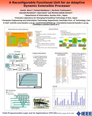
Generating and Executing Multi-Exit Custom Instructions for an Adaptive Extensible Processor Hamid Noori†, Farhad Mehdipour‡, Kazuaki Murakami†, Koji Inoue†, and Maziar Goudarzi† † Kyushu University, Japan ‡ AmirKabir University of Technology, Iran
Outline • Introduction • Overview of ADEXOR Architecture • Generating Multi-Exit Custom Instructions (MECIs) • Proposing an Architecture for the CRFU • Experimental Results • Conclusions and Future Work
Introduction • Motivation • Increase in manufacturing and NRE costs • Increase in design and verification costs due to more complexity • Shorter time-to-market • More required flexibility due to evolution of standards, user requirements, supporting multiple applications and etc • Our proposed approach • Generating custom instruction after chip-fabrication • Proposing multi-exit custom instructions • Proposing a reconfigurable functional unit with conditional execution using a quantitative approach
General Overview of ADEXOR Architecture • Phases • Design phase • Configuration phase • Normal phase
Generating Multi-Exit Custom Instructions • Multi-Exit Custom Instructions • Include hot directions of branch instructions • Include single entry but multiple exits
Detecting subgraphs in a HIS Moving instructions after checking data dependency (binary rewriting) Overwriting the entry node with mtc1 instr S1 S2 S2 S2 S1 S1 branch exit 1 mtc1 branch exit 1 branch exit 1 LS LS LS exit 2 exit 2 exit 2 Generating Multi-Exit Custom Instructions • Finding the largest sequence of instructions in the CFG • Checking the anti-dependence and flow-dependence and moving executable instructions to the head and tail(s) of MECIs • Rewriting the object code where instructions are going to be moved.
Generating Multi-Exit Custom Instructions • Tool Chain
CRFU Architecture: A Quantitative Approach • 22 programs of MiBench were chosen • Simplescalar toolset was utilized for simulation • CRFU is a matrix of FUs • No of Inputs • No of Outputs • No of FUs • Connections • Location of Inputs & Outputs • Some definitions: • Considering frequency and weight in measurement • CI Execution Frequency • Weight (To equal number of executed instructions) • Average = for all CIs (ΣFreq*Weight) • Rejection rate: Percentage of MECIs that could not be mapped on the CRFU • Mapping rate: Percentage of MECIs that could be mapped on the CRFU
Supporting Conditional Execution Selector-Mux
Synthesis result • Synopsys tools • Hitachi 0.18 μm • Area: 2.1 mm2 • Configuration bits: 615 bits • Delay
Experiment setup • 22 applications of Mibench • Simplescalr
Conclusion • Our experimental results show that by extending custom instructions over multiple HBBs the average speedup increases by 46% compared to the custom instructions which are limited to only one HBB. This is achieved in return for 83% more hardware and 20% more configuration bits. Utilizing connections with different length are helpful for supporting larger custom instructions with the available number of FUs.
Future work • Energy evaluation of the ADEXOR • Exploring the design space of CRFU architecture (To study the effect of number of inputs, outputs, FU on the speedup, area and power)
Introduction (1/2) • Efficiency and flexibility in embedded system design • Both are critical • Both are conflicting design goals • Custom hardwired feature for more efficiency (performance and energy) • Programmable feature for more flexibility • Design challenges for future embedded systems • More required efficiency (performance and energy) for future embedded systems • Higher manufacturing and NRE cost of new nanometer-scale technologies • Higher cost and risk in development • Shorter time-to-market
Introduction (2/2) • Custom instructions • Effective technique for improving efficiency • Custom functional units are required (manufacturing, NRE and design cost) • Our proposed approach • Generating custom instruction after chip-fabrication • Proposing multi-exit custom instructions • Replacing custom functional units with a reconfigurable functional unit with conditional execution
B1 S4 S8 S1 B5 B7 B10 B2 S5 J2 S9 S2 B6 B8 B11 B3 J1 S7 J3 S3 S6 B9 S10 B4 B12 Generating Multi-Exit Custom Instructions • Motivating example • adpcm loop
Generating Hot Instruction Sequence MECIs should not cross loop boundaries Sorting loop from innermost to outermost Reading HBBs and linking them to generate Hot Instruction Sequence Sort other remaining HBBs in ascending order considering their start address Function MAKE_HIS (objfile, HIS, start_addr) 1 if (HBB with start_addr is not included in previous MECIs) then read_add_HBB2HIS (objfile, HBB(start_addr), HIS) elsereturn; 2 switch last_instruction(HBB) 3 case (indirect jump, return or call):return; 4 case (direct jump): MAKE_HIS(objfile, HIS, target address of jump); 5 case (branch): 5-1 if (it is hot backward) thenreturn; 5-2 elsif (not-taken direction is hot) then MAKE_HIS(objfile, HIS, target address of not-taken direction) else return; 5-3 if (taken direction is hot) then MAKE_HIS(objfile, HIS, target address of taken direction) else return; 6 default: return; Generating Multi-Exit Custom Instructions
Generating Multi-Exit Custom Instructions • MECIs include fixed point instructions except multiply, divide and load. At most on store and five branches. • A MECI can have at most four exit points • branch with only one hot direction • indirect jump and return • call • hot backward branch • an instruction where its next instruction is non-executable. • If both directions of a branch are hot, both corresponding HBBs are added.
Proposing an Architecture for the CRFU • Design Methodology
Integrated Framework (1/2) • Integrated Framework • Performs an integrated temporal partitioning and mapping process • Takes rejected CIs as input • Partitions them to appropriate mappable CIs • Adds nodes to the current partition while architectural constraints are satisfied • The ASAP level of nodes represents their order to execute according to their dependencies
Integrated Framework (2/2) • Incremental HTTP • The node with the highest ASAP level is selected and moved to the subsequent partition. • Nodes selection and moving order: 15, 13, 11, 9, 14, 12, 10, 8, 3 and 7.
Effect of connections on mapping rate • By deleting the connections with length more than one, 24.2% of MECIs can not be mapped.
General Overview of ADEXOR Architecture • Main components • Base processor • 4-issue in-order RISC processor • Reconfigurable functional units (CRFU) • Coarse grain • Based on matrix of functional units (FUs) • Multi-cycle • Parallel with other functional units of the base processor • Read/write from/to register file • Functions and connections are controlled by configuration bits • Configuration memory • To keep the configuration data of CRFU for multi-exit custom instructions (MECIs) • Counters • Control read/write ports of register file and select between CRFU and processor functional units
Speedup CIs & MECIs • The number of inputs, outputs and FUs are the same • simpler connections and FUs and does not support conditional execution. • Area: 1.15 mm2 • Delay for a CI with a critical length of five is 7.66 ns. • Each CI configuration needs 512 bits. • The average number of instructions included in CIs (one HBB) is 6.39 instructions and for MECIs is 7.85 instructions.
Control Bits & Immediate Data • 375 bits are needed as Control Bits for • Multiplexers • Functional Units • 240 bits are needed for Immediates • Each CI configuration needs (308+204 = 615 bits)