Download
1 / 24
240 likes | 374 Views
ILC Damping rings. G. Dugan PAC TDR review 12/13/12. Outline. Requirements Configuration, parameters, operating modes Lattice Beam dynamics issues Emittance tuning and nonlinear effects Electron cloud effect Fast ion instability Technical systems RF Magnets and power supplies

E N D
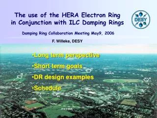
ILC Damping rings G. Dugan PAC TDR review 12/13/12 ILC Damping Rings
Outline • Requirements • Configuration, parameters, operating modes • Lattice • Beam dynamics issues • Emittance tuning and nonlinear effects • Electron cloud effect • Fast ion instability • Technical systems • RF • Magnets and power supplies • Vacuum, instrumentation and feedback • Injection/extraction • Conclusion ILC Damping Rings
Damping rings functional requirements • accept e- and e+beams with large transverse and longitudinal emittancesfrom the sources and produce the low-emittance beams required for high-luminosity production; • damp incoming beam jitter (transverse and longitudinal) and provide highly stable beams for downstream systems; • delay bunches from the source to allow feed-forward systems to compensate for pulse-to-pulse variations in parameters such as the bunch charge. ILC Damping Rings
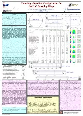
Ring Configuration Circumference: 3238 m, 2 x 710 m straights 5.6 μm-rad < γεx< 6.4μm-rad 14-pole wigglers : length 2.1 m, Bpeak2.2 T,period 30 cm =>24 ms > τx > 12 ms Phase trombone ± 0.5 λβ Chicane ± 4 mm pathlength 12 – 650 MHz RF cavities => σl = 6 mm Harmonic number 7022 e+ (future option) e- (baseline) e+ (baseline) ILC Damping Rings
Operating modes and ring parameters • Three ILC operating modes correspond to four DR configurations • Two modes utilize a 5 Hz repetition rate: low power baseline (1312 bunches/ring); and high luminosity upgrade (2625 bunches). • Third operating mode is at 10 Hz, with e- linac operated with alternating pulses: high energy for e+ production followed by low energy for collisions. • Shorter damping times necessary to achieve the same extracted vertical emittance in half the nominal storage time. ILC Damping Rings
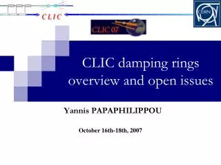
Ring lattice circumference chicane phase trombone extraction injection RF wigglers arc arc ILC Damping Rings
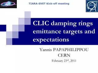
Arc cells Each cell contains : 1 - 3m dipole, θ = π/75 3 – quadrupoles 4 - sextupoles 3 - corrector magnets 1-horizontal steering 1-vertical steering 1- skew quad 2 beam position monitors 75-cells/arc BPM BPM ILC Damping Rings
Damping Wigglers • Wiggler straight • 2 wigglers/cell • 30 cells • 2.1 m wiggler • 1.5T< Bpeak< 2.2T • 54 @ 2.16T => τx=13ms (10Hz) • 54 @ 1.51T => τx = 25ms (5Hz) • 3 empty cells will accommodate 6 additional wigglers if required • H&V dipole corrector and BPM adjacent to each quad ILC Damping Rings
RF straight • RF • 2 cavities/cell • 22.4 MV => 6mm bunch length @ τx=13ms => for 12 cavities 1.9MV/cavity 272kW/coupler Lattice can accommodate 16 cavities if required Cavities offset so that waveguides of upper and lower rings are interleaved H&V corrector and BPM adjacent to each quadrupole ILC Damping Rings
Emittance tuning-1 Emittance in 3rd GLS, DR and colliders R. Bartolini Low Emittance Rings Workshop, Crete 3rd October 2011 Note that LS emittance results are for electron rings. CesrTA ATF ILC Damping Rings
Emittance tuning-2 • Measure and correct orbit using all steerings • Measure betatron phase advance (by resonant excitation) – and correct using quadrupoles • Measure coupling (by resonant excitation) and correct with skew quads • Measure orbit, coupling, and vertical dispersion and simultaneously correct with vertical steerings and skew quads Design: 2 pm ILC Damping Rings
Nonlinear effects • Magnet misalignments as on previous slide. • Magnet multipole errors based on PEPII and SPEAR magnet measurements. • Wiggler nonlinearities based on numerical wiggler field model, checked against Cesr wiggler field measurements. Dynamic aperture with specified magnet misalignments and field errors,and full Taylor map for wiggler nonlinearities Tune footprint Injected positron beam ILC Damping Rings
Electron Cloud Effect-outline • Vacuum chamber design to minimize photon absorption in the chamber • Vacuum chamber surface EC mitigation • EC buildup simulations to estimate ringwide average cloud density • Comparison with analytic estimate of instability threshold • Comparison with numerical simulations of coherent and incoherent emittance growth using CMAD ILC Damping Rings
DR Vacuum System Design • DR vacuum chamber has been designed with the help of a new photon tracking code (Synrad3D) developed for CesrTA • The code allows accurate determination of antechamber features to limit the number of photons absorbed within the vacuum chamber. • It also provides an accurate estimate of the sources of the photoelectrons which seed development of the electron cloud. Fully-absorbing photon stops Antechamber with slanted interior end to reduce photon backscattering Note that the vacuum chambers are shown rotated by 90o relative to their installed orientation. ILC Damping Rings
Vacuum chamber surface treatment forSEY suppression SEY, TiN, from CesrTA Mitigation Evaluation conducted at satellite meeting of ECLOUD`10 (October 13, 2010, Cornell University) SuperKEKB Dipole Chamber Extrusion DR Wiggler chamber concept with thermal spray clearing electrode – 1 VC for each wiggler pair. RFA current in wiggler, from CesrTA Y. Suetsugu Conway/Li ILC Damping Rings
Electron cloud density from buildup simulations Based on photon rates from Synrad3D; Peak SEY = 0.94 (TiN) Cloud density is average over 20 sigma around the beam, just before the pinch, in units of 1011/m3. Length is in meters. Dipoles have no grooves. Trapping in quadrupoles Solenoids in drifts produce 100% suppression of cloud near the beam Crittenden EC Suppression by Wiggler Electrode: Wang Wang ILC Damping Rings
Comparison with instability thresholds Analytic estimate (in coasting beam approximation) for the electron cloud density at threshold (Jin,Ohmi): [Jin, Ohmi]: H. Jin et al., “ Electron Cloud Effects in Cornell Electron Storage Ring Test Accelerator and International Linear Collider Damping Ring,” Jpn. J. Appl. Phys. 50, 026401 (Feb. 2011). ILCDR ringwide density/threshold density ~ 0.35/1.5 ~ 0.23 ILC Damping Rings
CMAD simulations of EC-induced emittance growth There is a clear threshold to exponential growth between (3 – 5) x1011/m3cloud density Smooth focusing lattice Real DR lattice, 0.35x10¹¹/m3 cloud density Incoherent emittance growth at 0.35x10¹¹/m3is about .001 in 300 turns Smooth focusing lattice • Incoherent emittance growth at 0.35x10¹¹/m3 is about .0016 in 300 turns • The store time is about 18,000 turns • The emittance growth during the store time should be about 10%. • Radiation damping is not included. Damping time is about 2,000 turns. ILC Damping Rings
Fast Ion Instability in Electron Damping Ring No gap 43 RF bucket gap Simulation Codes confirmed by experimental results at ATF-DR, CesrTA, SPEAR3 and low emittance SR Rings • Control of this instability requires • Low base vacuum pressure ~ 10-7 Pa • Gaps (43 RF buckets) between mini-trains • Bunch-by-bunch feedback system with a 20 turn (~0.2 ms) damping time ILC Damping Rings
Technical systems: RF • 12 650 MHz SCRF cavities, operating CW at 4.5K • Gradient 6-8 MV/m • 6 klystrons, peak power 0.7 MW CW • 3 Operating modes: • Baseline: 2 MW RF power, 10 cavities, 14 MV RF • 10 Hz: 3.8 MW RF power, 12 cavities, 22 MV RF • Upgrade: 3.8 MW RF power, 12 cavities, 14 MV RF ILC Damping Rings
Technical systems: Magnets and Power supplies • Superconducting magnets • 54 superferric wigglers, operating at 4.5K • Design based on Cesr-c experience • Shorter period, higher field than RDR spec. Conventional magnets Power supply system design based on “bus” powering of DC-to-DC converters for individual magnet supplies. ILC Damping Rings
Technical systems: vacuum and instrumentation Vacuum system: • Antechambers and electron cloud mitigation as presented in slides 13, 14. • Base pressure 10-7 Pa from • NEG strips in the dipole and wiggler antechambers. • Localized ion pumps (~5 m) and TiSP pumps. • Sufficient pumping speed to handle conditioning requirements. • Sliding joints cover bellows to control impedance Instrumentation system: • BPMs with specifications given in slide 10. • Tune trackers • Visible and/or X-ray SR light monitors • Current monitors • Beam-loss monitors • Fast feedback systems to control coupled-bunch instabilities • Bunch-by-bunch, all 3 planes • Bandwidth > 650 MHz • Damping time ~0.2 ms • 1 kW power ILC Damping Rings
Technical systems: Injection/Extraction • Individual bunch injection/extraction (in the horizontal plane) requires very fast, very stable kickers • Extraction kicker pulse rate 1.8 MHz (3 MHz for lumi upgrade) • For 6 ns bunch spacing, require rise/fall time ~ 6 ns (3 ns for lumi upgrade) • 42 strip-line 50 W kicker modules, 30 cm long, 30 mm gap • Total kick angle ~0.6 mrad (10 kV pulse on each electrode) for extracted beam • Kicker jitter tolerance (kick amplitude stability) < 5 x 10⁻⁴ • Tests at ATF with FID pulser have demonstrated required rise/fall times, jitter tolerance • Kicker impedance issues still to be resolved Good field quality is required for the pulsed magnets (kicker, septum) in the extraction channel to preserve the ring emittance after extraction. Remainder of injection/extraction system is conventional and straightforward. ILC Damping Rings
Conclusion • The TDR design for the ILC Damping rings has been reviewed. • The functional requirements, the ring configuration, and the principal parameters and operating modes have been described. • The lattice design has been outlined. • The leading beam dynamics issues impacting ring performance have been discussed: • Emittance tuning and nonlinear effects • Electron cloud effect • Fast ion instability • The key elements of the principal technical systems have been described: • RF • Magnets and power supplies • Vacuum, instrumentation and feedback • Injection/extraction ILC Damping Rings