Download
1 / 18
180 likes | 366 Views
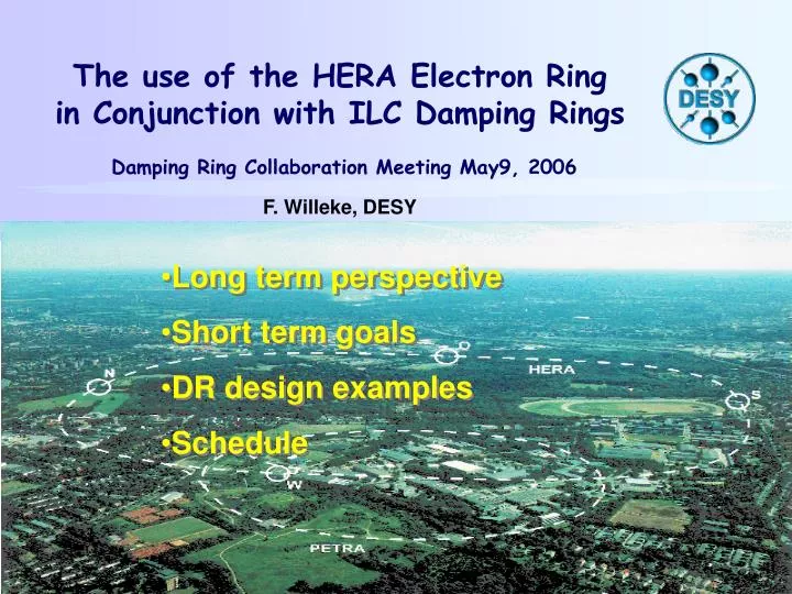
The use of the HERA Electron Ring in Conjunction with ILC Damping Rings Damping Ring Collaboration Meeting May9, 2006 F. Willeke, DESY. Long term perspective Short term goals DR design examples Schedule. ILC Damping Rings. Most challenging accelerator problem:

E N D
The use of the HERA Electron Ringin Conjunction with ILC Damping Rings Damping Ring Collaboration Meeting May9, 2006F. Willeke, DESY • Long term perspective • Short term goals • DR design examples • Schedule
ILC Damping Rings Most challenging accelerator problem: • Very large beam currents (0.5A) • Very small equilibrium emittance 1pm • Strong damping • Fast kickers required • Strong transient beam loading • Very broadband feedback systems • Operation with high intensity positrons … The challenging issues are coupled (small emittance & high intensity) There is a non-negligible risk that it might be difficult achieve The performance goal of the damping rings. Need design margins, impacts on cost, … Decision on the size of the damping rings: 6 km (Snowmass 05)
ILC Damping Ring & HERA Damping Ring Collaboration has concluded that the optimum circumference for the ILC damping rings is about 6km it turns out, there exists one accelerator ring which matches almost perfectly the major design parameters of the ILC damping ring. The HERA Electron Ring • circumference of 6.36 km. • magnets with good field quality • large aperture • sophisticated beam diagnostics, • superconducting RF, • a well conditioned copper vacuum pipe, • build-in beam-based alignment capabilities in addition outstanding expertise of dealing with large electron rings strong interest in low emittance lattice. No plans for any other use of HERA This is a remarable constellation! How make we make best use of it?
Four-Stage Approach in Using HERA for the ILC Damping Rings Stage 0: HERA will be maintained as is (approved) Stage I: Preparing the existing accelerator for its use as a DR Stage II: Demonstration of the most pressing accelerator physics issues of the DR with HERA with moderate R&D-scale investments Stage III: Modifying HERA into one of the ILC damping rings, commission it and demonstrate the required performance Stage IV: Disassemble and reinstall the ring at the ILC site, re- commissioning and operate it as one of the damping rings
Stage III (long-term perspective) Implement ILC DR in the HERA tunnel prior to re-installation at final destination. using many of the existing components (magnets beam pipes ) satisfactory damping ring lattice. Components replaced only if obviously insufficient or if investigations beam test will tell so • save costs by using existing components, • allow an early feasibility and performance check of the damping rings to make sure that the machine performs as required to reach high luminosity quickly and reliably in the ILC. • This even could be done before large investments are made. • Most of the HERA components are likely sufficient for a demonstration of feasibility of the damping ring concept, even if one would prefer to replace some of them for a reliable production machine. • Proceeding this way would leave open the option for alternative damping ring design at small penalty. Moreover, carrying over the experience from a previous version of the accelerator should be advantageous as well B-factories examples of the benefit of being able to carry over expertise from previous versions of the accelerator to the new machines) This is a unique advantage!
Stage II (medium term perspective) aim for the demonstration of the feasibility of some of the most challenging DR design issues by performing accelerator experiments. These experiments could include for example: • the demonstration of high positron beam current of (250-500) mA without detrimental effects on vertical beam emittance • achievement of the required small vertical beam emittance in the order of 10-12 m, • the demonstration of effective beam based alignment techniques necessary to maintain the DR performance efficiently. believed to be achieveable for a demonstration experiment with a moderate R&D effort and with modest investments and additions to the present accelerator. In order to define, to prioritize and to work out this demanding study programme, it is envisioned to involve the GDE and the strong international damping ring collaboration who would partly assume ownership of the accelerator. Extended DR collaboration (DESY, EU-funding) provide high-tech equipment and improvements Examples of needed systems: • Broad-band transverse and longitudinal damper systems, • Transient beam loading compensation feedback, • Low emittance measurement techniques, • Improved higher order mode damping of the s.c. cavities, • Beam position monitor electronics with high resolution and features needed for low emittance tuning. Coordination with other existing or planned damping-ring test facilities avoiding duplication and waste of resources. smaller ring tests: • fast kickers, • wiggler prototype, • measurement equipment • Special beam pipe surface structures Remedies for problems and improvements of insufficient design also would be tested better in smaller rings where a smaller number of equipment components needs to be supplied prior to ultimate (expensive) performance tests YOUR INPUT NEEDED !!
Stage I (starting in 2007) Preparing HERA for stage II • Need new injection line • Need to remove nc cavities from the ring • Close the tunnel in the exp. Halls with shielding blocks • Small modification of the lattice in the straight section
HERA Hardware HERA as is can be used for many important tests and experiments without large modifications Many HERA Components could be used for the final ILC damping rings (with moderate modernization and improvement: Dipole Magnets, Quadrupole magnets, Sextupole Magnets, Correctors, Powersupplies, sc cavities, RF klystrons, RF ps+Modulator vacuum chamber, NEC and other vacuum pumps polarimeters Other equipment would have to be provided later High resolution BPM, fast kickers, broadband feedback, RF feedback wigglers
Possible Not-too-Far-Term DR Studies in HERA ISSUE Additional Equipment Needed • De-install n.c. 500MHz cavities, • RF feedbacks, • 250MHz bandwidth MB damper • improved HOM couplers at SCC • Improved BPM electronics • Additional BPMs • Additional BBA circuitry • Low e Measurement equipment • Storage of 250mA of positron with a bunch-spacing of 6-16 ns, • study of electron-cloud issues, testing of remedies • Demonstration of 1pm vertical emittance • Demonstration of effective bba procedures • Polarization test measurements To be discussed and closely co-ordinated with GDE and DR collaboration!
Examples for DR Lattices based on HERA Octant structure with one dipole surrounded by 2 empty cells and 2 Wiggler sections F-drift-D-O-D-drift-F (this solution provides all the dipoles for 3 damping rings) Octant Structure with FODO cell and 2 wiggler sections in the straight
Possible Wiggler Section 12 periods a 80cm, B~1T, 16 wiggler sections, 120m activ length
Time Line now - 6/2007 HERA e-p Operation, forming of DR Collaboration 6/2007- 6/2008 New e-Extraction from DESYII 7/2008 -7/2009 Install new beam line DESYII to HERA WL300 De-install NC cavities, 8/2009-9/2009 Commission new injection 10/2009-6/2012 DR Test-runs with HERA „as-is“ ILC damping ring design 7/2012? ILC Project Start 7/2012-7/2014 Procurement of new DR components 7/2014-7/2015 Installation 7/2015-7/2017 DR Commissioning 7/2017-12/2018 De-installation-Re-installation at ILC site 1/2019 DR re-commissioning
possible next steps … Informal discussions with GDE (done, in progress, successful) Informal discussions with potential collaborators (in progress, so far quite successful) Informal discussion with technical groups (in progress) DR Ring Group at DESY started (May 2006) Preparation of „white book“, internal discussions DESY (May 2006) Discussion within EuroteV/Care FP7?(May 2006) Proposal to GDE R&D Board (May 2006) Preparation of DESY Vorhaben for new Injection line (May-August 2006) DESY Vorhaben New Beam Line Submission (August 2006) DESY internal Resources planning and coord. (June-December 2006) Preparation of MOU between DESY & Collaborators (June-December 2006) DR MOU DESY & Collaborators (June-December 2006)
Immediate Consequences • Plans for using HERA(e) components must be carefully revised • Possibility of producing positrons at DESY must be preserved • Cryogenic supply for SC Cavities must not be cut
Conclusions This could be an exciting project, It should be of considerable mutual benefit to DESY and the ILC Immediate resources necessary to allow occasional test runs are very small (compared to what is foreseen to maintain the HERA complex) There is work on planning and designing to do within the next few months: help is welcome