Download
1 / 13
130 likes | 131 Views
This update covers the recent progress made in the mechanical alignment, diagnostics, and laser system of the CALIFES project. The alignment of components and correction of parameters have been carried out to ensure optimal performance. Additionally, updates on the laser system, including frequency conversion and transportation efficiency, are discussed.

E N D
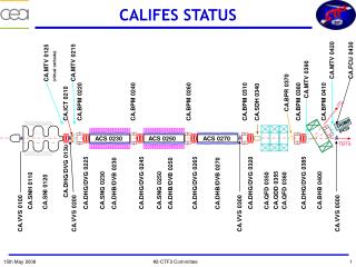
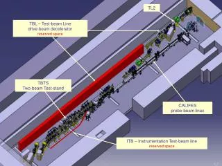
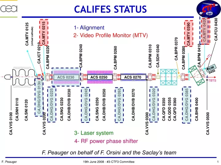
ITL DUM 0450 ACS 0230 ACS 0250 ACS 0270 TBTS CALIFES STATUS 1- Alignment CA.FCU 0430 CA.MTV 0420 CA.MTV 0125 (virtual cathode) CA.MTV 0215 CA.MTV 0390 2- Video Profile Monitor (MTV) CA.BPR 0370 CA.ICT 0210 CA.BPM 0410 CA.SDH 0340 CA.BPM 0240 CA.BPM 0310 CA.BPM 0220 CA.BPM 0260 CA.BPM 0380 CA.DHG/DVG 0130 CA.DHB/DVB 0250 CA.DHG/DVG 0245 CA.DHG/DVG 0225 CA.DHG/DVG 0385 CA.DHB/DVB 0230 CA.DHG/DVG 0320 CA.DHB/DVB 0270 CA.DHG/DVG 0265 CA.QFD 0350 CA.BHB 0400 CA.SNG 0230 CA.QFD 0360 CA.SNG 0250 CA.QDD 0355 CA.SNH 0110 CA.SNI 0120 CA.VVS 0300 CA.VVS 0200 CA.VVS 0100 CA.VVS 0500 3- Laser system 4- RF power phase shifter F. Peauger on behalf of F. Orsini and the Saclay’s team
CALIFES STATUS: Mechanics/Alignment • Work done on week 21 • End of linac alignement: • new set of measurements confirmation of problem on parameters of LIL section ACS0230 and on values of MTV 0420 (Dump), and ICT component was missing • (all other components parameters are OK) • correction of vertical position of ACS0230 • correction of position for MTV0420 (an error of dimensioning of the square is at the origin of the mechanical problem. The position was rectified) • Adjustment of correctors position on all supports (CA.DHG/DVG130-…-0385) • We noticed an important difference of level between accelerating section ACS0230 and the elements upstream and downstream a checking of level between the beam axis and the sphere highlighted a difference of more than 1.5 mm between the measured value and the value used like parameter. The position of ACS0230 was corrected in consequence. • CALIFES is now aligned • Mechanics : Installation of the mirror in the laser chamber near the RF Gun OK • Cabling: - connections of CA.DHB/DVB0230 to be finished (CERN)
CALIFES STATUS: Diagnostics MTVs (1/2) Work done on week 21 • CA.MTV0390 (2nd) is tuned optically • Motorization of screen, wheel with filters and retractable lenses works locally, • The interfacing is in progress (CCD box in installation by Francis, discussion on the C/C with Stephan Burger), • An additional interface device will be necessary for the wheel with filters and lenses. Camera, lighting and motorization of screen are directly interfacable with CCD box. • CA.MTV0420 (3rd) is also tuned optically • Incline the CCD improves the depth of field clearly CCD perpendiculaire CCD tilt by 10.5°
CALIFES STATUS: Diagnostics VPMs (2/2) Work done on week 21 Evolution of the magnification versus the position on the screen • An image processing seems necessary to correct the variation of the magnification, • The motorized diaphragm works locally but an adaptation will be necessary with CCD box (different voltages), • The upper light shielding has also to be built, • The radiation shielding have to be foreseen (support for Pb bricks). • CA.MTV0215 (1st)is in a close status as the CA.MTV0420 (3rd), but no tilt of the installed CCD camera (no critical specifications)
CALIFES STATUS: Laser system (1/3) • Work done on week 21-23 : • Frequency conversion: • by measurement on KTP (crystal) with only Amp1 at low power, we confirmed that with no (or little) “interpulse background”, the conversion efficiency (IR to green) is nearly what is expected with SNLO software simulation (the green beam diameter was probably between 120 and 150µm). • SNLO simulation can only take into account a M²=1 beam; increase of M² doesn’t affect so much the KTP result because of high acceptance angle; but it should affect the BBO result due to low acceptance angle coming from high walk off. That is probably the reason of the difference between the simulation and the experiment on that crystal. • Best result in term of UV energy is ~30 nJ/pulse (before transportation), with Amp2 Off and Amp1 at 65A,with IR energy ~ 0.4 µJ green energy ~ 0.2µJ (efficiency 45% to 50%) UV energy: ~30 nJ (efficiency ~15%). • With 25% loss expected in Pulse Picker and 25% loss in transport: • ~15 nJ on the photocathode
Temporal window of 2µs (much more than nominal), thus 3000 shootings of ~ 5nJ (instead of 30 nJ !! UV beam passing through the preparation chamber, and materialized on the CLEX wall UV beam on photocathode CALIFES STATUS: Laser system (2/3) • Transport and alignment: • The 4 lenses of the transport “under the roof” and the UV mirrors have been installed • UV Beam path on the PI table is aligned down to the photocathode for the first time ! • (the exact photocathode was in operating position). • The scan on a disk of more than 15mm diameter on photocathode plan is possible horizontally and vertically, with mirror on New focus mount.
CALIFES STATUS: Laser system (3/3) • Work planned on week 25 : (only 1 day CLEX closed for UV beam ?) • Try to re-obtain 30nJ • Check of the camera with the phosphorous plate in the laser room, with the equivalent power than will be available on the virtual cathode ; check again the UV image, • Install the final line in the laser room first without and then with it, • If possible: install the pulse picker • During the time available for UV laser in Clex (could be for one full day?): • Re-adjust the alignment, • Check the image with the camera on the virtual cathode plane, • Check of the output of the photodiode (+”integrateur-bloqueur”) ; the synchronisation signal has to be checked before, it has to arrive roughly at the same time than the laser macropulse.
CALIFES STATUS: Phase Shifter (1/4) • Work done on weeks 20->25 : • High power vacuum phase shifter: • Drawings modifications of mode converters following the brazing test done on prototype (April 2008): many iterations between CEA, the machining company and the brazing company • The machining supplier who was responsible for the whole process in the initial order admitted that he will not be able to manage the chemical and brazing operations for the fabrication of the two final mode converters • The machining company has already spent 1.5 times his initial budget and has ~1 year delay… • Redefinition of the initial contract has to be done : CEA would manage directly the brazing company • Negotiation for the reduction of the initial contract price • New order to be generated with the brazing company who have already produced the mode converter prototype
CALIFES STATUS: Phase Shifter (2/4) • Work done on week 24 : • Alternative solution in case of additional delay: • Two high power phase shifters are available at CEA now. They come from the ALS (Accelerateur Lineaire de Saclay), stopped in 90’s • Worked at 2.99855 GHz, 3 MW, 10 µs, 500 Hz, under SF6 at 1 bar (absolute pressure, air pumped) • Made of a quartz rod inserted into a 90° H-bend. The rod translate manually by a worm drive.
CALIFES STATUS: Phase Shifter (3/4) • Work done on week 24 : • Low level RF measurements • 82.7 degrees in 104 turns • 0.79 degrees per turn • Transmission > 0.16 dB • Reflexion < -20 dB S12 amplitude (dB) Frequency (Hz) S11 amplitude (dB) S12 Phase (dB) Frequency (Hz) Frequency (Hz)
CALIFES STATUS: Phase Shifter (4/4) Esurfmax = 7.2 MV/m @ 15 MW Esurf (45MW klystron output)~ 6 - 7 MV/m in SF6 at 4 bars This solution would require two RF windows, additional waveguides and mechanical supports
CALIFES STATUS: Conclusion • Final alignment of the linac OK • MTVs (Video Profile Monitors) tuned optically, good results with CCD tilted, motorization OK, electrical adaptation and Control Command tasks to plan • First transport of the UV laser beam down to the photocathode, energy still too low • Redefinition of the initial contract for the circular phase shifter : CEA would manage directly the brazing company. Alternative solution proposed