Download
1 / 21
210 likes | 223 Views
High Power RF for CALIFES. General Layout of the RF system High Voltage Modulator 3D Layout of RF Network RF Power Phase Shifter and 4.5 dB Power Splitter Transient behaviour of gun and LIL sections. Already installed in CLEX (J. Mourier, G. Dispau).

E N D
High Power RF for CALIFES • General Layout of the RF system • High Voltage Modulator • 3D Layout of RF Network • RF Power Phase Shifter and 4.5 dB Power Splitter • Transient behaviour of gun and LIL sections
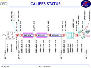
Already installed in CLEX (J. Mourier, G. Dispau) General Layout of the CALIFES RF System 14.5 MW → 12.5 MV/m 23.5 MW → 16.5 MV/m 23.5 MW → 16.5 MV/m 6.5 MW
Highest S-band peak power klystron procured by Thales: 45 MW RF power during 5.5 µs • Five integrated cavities klystron, vertical position • Electromagnetic beam confinement by solenoid • Collector and body water-cooled • Output waveguide pressurized by SF6 at 4 bars (absolute pressure) TH2100C Klystron Delivery time for klystron and solenoid: 04.04.08 (CERN)
High voltage modulator • Procured by Puls-Plasmatechnik GmbH (Germany) • Capacitor charging unit 45 kV / 8 kJ/s from PPT/Poynting • Thyratron CX1836A from EEV for high voltage switch • Pulse Forming Network (PFN): 4Ω impedance, 2 lines in parallel, 2 x 18 cells (30nF/2µH each) • - Inductance = single layer coil + aluminium core • - mutual coupling between the inductances • Pulse transformer ratio 1:15 and tank with x-y-z frame from Stangenes • Associated power supplies (magnet, heater, ion pump) • Transport system to remove the klystron in the maintenance area • Control system based on a PLC SIEMENS S7 300, with ethernet interface and “fetch and write” protocol for remote communication Better approximation of a rectangular pulse shape (Guillemin type E network [1]) Pulse Forming Network Klystron tank Triaxial cable Thyratron [1] Glasoe and Lebacqz: « Pulse Generators », MIT Radiation Lab Series, vol. 5, McGraw-Hill Book company, New York, 1948
Done the 8-9th of November 2007 with CEA and CERN (S. Curt, G. McMonagle): Factory test of the modulator Very good results for the pulse quality measured at low voltage (250V) after the pulse transformer on a 900 Ω dummy load flat top = 6 µs and ripple = +/- 0.23 % rise time = 0.95 µs, fall time = 1.6 µs, FWHM = 9.65 µs, Width at 75% = 8.97 µs Pulse to pulse stability OK measured value = 0.1 %, at 43 kV – 5.5 kA on 5.4Ω dummy load before pulse transformer at 0.3 Hz because of temperature drift of the load Pulse length too long from 8.97µs to 7.6 µs at 75% of height because of klystron acceptance remove one or two capacitances on each line Reverse voltage too high measured value = 24% specified value 70kV/305kV = 23% Vkly Ikly
Delivery at CERN (week 47) • Mechanical installation (week 48 and 49) • racks and tank installed and connected • water cooling and line voltage installed by CERN • installation of a spare TH2100C klystron S/N 094011 with solenoid and PPT lead shielding • Test of the transportation of the tank+klystron+lead shielding to the maintenance area OK Installation of the modulator in CLEX • Control system • local control tested and explained to CERN • remote control: discussion on the connection and structuring the data • Calibration • setting and calibration of all the auxiliary Power Supplies (PS) with the PLC values • problem with ion pump PS: defect on the HV cable → replaced by a CERN PS • Tests • machine and person interlocks OK • Tests of the klystron in diode mode with loads on RF ports • High voltage up to 38kV / 2 Hz PFN voltage which corresponds to 250 kV – 280 A on the klystron • inverse voltage < 3% : OK • pulse length = 7.67 µs at 75%: OK • flat top = 5.5 to 5.7 µs: OK S. Curt, JL. Jannin, J. Marques, G. Rossat, G. Yvon
Ikly Vkly VDC supply • Pulse quality problem : ripple on flat top too high = +/- 4 % instead of +/- 0.25% • long wave on the flat top • high frequency noise at the beginning of the voltage pulse Modulator: Pulse quality problem • Expertise & solutions: • for the long wave ripple: mismatch between PFN or thyratron and triaxial cable • → tune the PFN and/or add a RC series combination • for the HF noise: measurement problem with Voltage Divider (VD) : • can be due to fast oscillation between the load (klystron) and the resonator composed of the capacitance of the VD and a parasitic self • other possibilities: parasitic current between mass, antenna effect with last PFN inductance, unstable scope • Start with RF if possible: phase measurement = best way to check the ripple • Next possibility to start and test the modulator : mid March 2008→ PPT is confident to reach the specifications
RF Network layout HV MODULATOR + KLYSTRON LASER BEAM HOLES (x5) between klystron gallery and tunnel e- BEAM DIAGNOSTICS LIL3 LIL 2 LIL 1 N. Chritin, P. Girardot, G. Rossat RF GUN
CABLES BOC CAVITY RF WINDOW 300 mm 1070 mm CIRCULATOR COUPLER 540 mm 200 mm KLYSTRON COUPLER 2515 mm (1616 mm) 511 mm 4.5 dB SPLITTER RF WINDOW 1000 mm 476 mm SF6 PHASE SHIFTER SF6 VARIABLE ATTENUATOR 1317 mm 490 mm 1000 mm 2000 mm 1000 mm 723 mm 987 mm 1000 mm 890 mm 1000 mm 1300 mm VENTILLATION 1000 mm 1000 mm 1616 mm 1562 mm VACUUM PHASE SHIFTER 1000 mm 3000 mm
COUPLER RF WINDOW 3 DB SPLITTER 477 mm 3 DB SPLITTER 231 mm 477 + 87 = 564 mm 452 mm 1753 mm 111 mm 283 mm 111 + 87 = 198 mm GUN 231 mm (283 mm) 3000 mm LIL 3 182 mm 3000 mm 1788 mm 283 mm 2978 mm Two arms in phase in the two inputs of the gun Additionnal lentgh of waveguide to compensate the 90° phase shift of the splitter LIL 2 3000 mm 3000 mm 2721 mm 1148 mm 3000 mm LIL 1 2089 mm 1143 mm GUN
Main specifications of the phase shifter • a variation of 1° of the RF phase in the bunching section induce a variation of 20% of the rms bunch length σZ Power Phase Shifter on the Bunching Section Parmela simulation in single bunch • Mechanically feasible by three circular waveguides • Principle: phase shift by variation of guided wavelength • Mechanical design Based on A. Grudiev and SLAC concept • TE10□ - TE01O mode converter to avoid surface electric field and risk of breakdown 350 kg E max = 8.1 MV/m for 30 MW 1 m
Fabrication of mode converter • First try of fabrication : milling operation OK but leakage after brazing: bad behavior of the brazing alloy Test of machining in CuC2 Test of machining in aluminium • Review of the whole process with validation tests for the brazing operation and milestones between each key operation Rectangular waveguides and flanges CLM Additional machining & cleaning Additional machining & cleaning Brazing ~860°C Brazing ~1000°C Cleaning CERN Thermal treatment Final milling Pre-milling Raw material CuC2&316 LN Additional machining & cleaning Brazing ~780°C High power tests in CTF2 Cold RF tests Brazing ~810°C CERN Test of brazing on samples Test of brazing on scale 1 prototype CEA ABMT
Fabrication of sliding circular waveguides • Turning operations made by CLM in two steps • Pre-machining • Thermal treatment at 250 °C for CuC2 and 950°C for 316L • Final machining Bellows Bellows Cooling circuit Welding collar Flange Fixed tube n°1 Moving tube n°2 Fixed tube n°3 • Brazing operation at CERN • Final mounting and welding of bellows Delivery time :Sept. 2008, commissioning Oct. 2008
More about power phase shifter… Frame for transportation in vertical position Cradle for lifting and handling Holding tool of fixed tubes Motor driven phase shifter Control command synoptic Siemens Stepping motor, 4 Nm, 1000 steps per turn, 1 à 2 kHz Rose & Kriger Linear unit, 4 mm per turn, accurary 0.2 mm Security switch
4.5 dB Power Splitter • One 4.5 dB power splitter is not available in the RF Network and is not procured by the industry • RF Simulations and mechanical design made by CEA and fabrication made by CERN Main characteristics E Field 2 1 4 3 Mechanical design Bandwidth
Transient simulations: filling of LIL section with RF pulse from BOC • Simulation of the temporal response of the BOC and the TW section for field set up: • solve envelope differential equation by Runge-Kutta integration Specific code developed (A. Mosnier) Slope phase step: 1µs Quasi steady state field reached in LIL sections Filling BOC: 3.2 µs Flat top BOC: 1.3 µs Flat top RF klystron pulse: 5.5 µs • Phase step of 1 rad and linear variation from 1 to π rad • Power multiplication factor = 1.95 → 45 MW x 1.95 = 87.7 MW at the output of the BOC cavity • Drive frequency: 2.99855 GHz + 150 kHz for constant phase during BOC flat top
Transient simulations: effect of beam loading in multibunch operation • The train of (short) bunch is assumed as a sequence of δ-function current pulses • The transient beam loading is calculated by introducing amplitude and phase jumps in the cell excitation at each bunch traversal through the cell n • The propagation of these induced waves through the structure (with dispersive effects) between the bunch time intervals are calculated Einj = 5 MeV, 32 bunches, Qb = 0.6 nC, Bunch spacing = 0.666 ns « out-of-phase » acceleration: 12.8 MV/m (14.1 MW) and Φ=-88°: Emax =22.6 MeV, ∆E=2.1 MeV Φ=-54.2 °, ∆Φ=1.9 ° @ 1.5 GHz 15.2 ° @ 12 GHz Bunch 1 Bunching section Phase (deg) Energy (MeV) Bunch 32 • For the whole linac, with 32 bunches of 0.6 nC spaced by 0.666 ns: • Maximun energy = 170 MeV • Energy drop between first and last bunch: ∆E = 11.3 MeV = 6.6 % > +/- 2% specified • Phase drop between first and last bunch: ∆Φ= 2.4° @ 1.5 GHz ∆Φ = 19.2° @ 12 GHz > 10° specified Cell Cell « on-crest » acceleration 16.5 MV/m (23.4 MW) and Φ=-3°: Emax =79 MeV, ∆E=4.6 MeV Φ=11.1 °, ∆Φ=0.5 ° @ 1.5 GHz 4 ° @ 12 GHz Accelerating section Phase (deg) Energy (MeV) Still need to reduce the bunch charge to meet the specifications…
Transient simulations: Filling of Gun with RF Pulse from BOC (m) V1 V2 V3 M12 M23 M13 • Simulation of the temporal response the gun for field set up for the first monopole bandpass modes (π/2, π, 2π) • reach steady state? … Mix between modes?... • COMSOL eigenfrequency analysis coupled with equivalent circuit : solve envelope differential equation by Runge-Kutta integration (M. Desmons-CEA) abs(Ez) on beam axis @ Pcoax=1W Hphi @ Pcoax=1W at 2.998551GHz freq1: 2π mode freq2: π/2 mode freq3: π mode Working mode Ez1max Ez2max Ez3max Equivalent circuit for shorter computed time Ez1phase Ez2phase Ez3phase The beating between the 3 modes becomes very low after 2000 of RF period = 0.66 µs Eg direct Eg reverse (m)
Response of the gun to a BOC RF pulse Ez1max Ez2max Ez3max 90% of max. field at injection time Ez1phase Ez2phase Ez3phase Eg direct Eg reverse T ( us ) • Recall: in the 32 bunches mode, the train length is only 32 x 0.66ns = 21 ns ! • Possibility to increase the peak power (and so the gradient) in LIL sections by doing a partial filling of the structure → to be studied this year
Particle-In-Cell Simulations • Finite Difference Time Domain (FDTD) code developed at CEA Saclay (R. Duperrier) • Solve Maxwell equations in a given structure: calculate the fields induced by the beam in addition with the applied field (standing or travelling wave fields, static fields) • Take into account the transient beam loading, the space charge forces, the intra-bunch and long range Wakefields • Compute the energy loss, the energy/phase spread and the emittance degradation • Can simulate the gun and the LIL sections • Cluster available at CEA Saclay for parallelized calculation Transverse Electric Field Ex (V/m) in the RF Gun at 0.5 nC Energy dispersion in the gun : ~ 2 ‰ (1) • Wakefield simulation in the LIL sections → to be done this year (1) R. Duperrier, Compression de paquets pour CTF3, Journées Accélérateurs de la SFP, Roscoff 2005
Conclusion • HV modulator partially tested and accepted at factory, installed and started in CLEX • Pulse quality to be improved : to be done by PPT in end March / April (not the critical path for schedule) • 3D layout of RF Network done • Still a lot of procurement to do • Power phase shifter • copper pieces machined (milling and turning operations OK) • Brazing problem : new procedure of fabrication with validation steps (brazing tests on a scale-one prototype) • new results of beam dynamic simulations for multi-bunch operation with updated CLIC parameters • Suite of specific codes developed to compute the transient behavior of the RF accelerator cavities • useful for commissioning and higher performances evaluation of CALIFES Very good collaboration with CERN team ! Thank you for your attention …