Download
1 / 26
300 likes | 435 Views
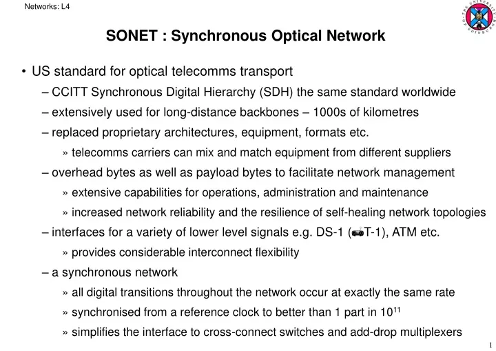
SONET : Synchronous Optical Network. US standard for optical telecomms transport CCITT Synchronous Digital Hierarchy (SDH) the same standard worldwide extensively used for long-distance backbones – 1000s of kilometres replaced proprietary architectures, equipment, formats etc.

E N D
Networks: L4 SONET : Synchronous Optical Network • US standard for optical telecomms transport • CCITT Synchronous Digital Hierarchy (SDH) the same standard worldwide • extensively used for long-distance backbones – 1000s of kilometres • replaced proprietary architectures, equipment, formats etc. • telecomms carriers can mix and match equipment from different suppliers • overhead bytes as well as payload bytes to facilitate network management • extensive capabilities for operations, administration and maintenance • increased network reliability and the resilience of self-healing network topologies • interfaces for a variety of lower level signals e.g. DS-1 (T-1), ATM etc. • provides considerable interconnect flexibility • a synchronous network • all digital transitions throughout the network occur at exactly the same rate • synchronised from a reference clock to better than 1 part in 1011 • simplifies the interface to cross-connect switches and add-drop multiplexers
Networks: L4 • Uses a 51.84 Mbps signal as its basic building block • time-division multiplexes these basic signals into higher-speed signals • STS-n : (Electrical) Synchronous Transport Signal level n • OC-n : Optical Channel level n • bit format of STS-n and OC-n is the same except for scrambling of the optical signal bits to aid timing recovery
Networks: L4 DS1 Low-Speed Mapping Function DS2 STS-1 CEPT-1 51.84 Mbps DS3 Medium Speed Mapping Function STS-1 44.736 OC-n STS-n STS-3c STS-1 Mux E/O Scrambler CEPT-4 High- Speed Mapping Function STS-1 STS-1 139.264 STS-3c STS-1 STS-1 High- Speed Mapping Function ATM STS-1 150 Mbps • SONET tributaries are the input streams multiplexed together
Networks: L4 Primary Multiplex Eg. Digital Switch 24 chan PCM M23 Multiplex x7 M12 Multiplex x4 DS2 6.312 Mbps DS3 44.736 Mbps DS1 1.544 Mbps 1 M13 Multiplex DS3 44.736 Mbps 28 CEPT 1 Primary Multiplex Eg. Digital Switch 30 chan PCM 3rd order Multiplex x4 CEPT 4 2nd order Multiplex x4 4th order Multiplex x4 34.368 Mbps 8.448 Mbps 2.048 Mbps 139.264 Mbps • the US hierarchy: • the European hierarchy:
Networks: L4 • tributaries such as DS-1 use free-running clocks • not synchronised with the higher-level network • accuracy specified as just 20 parts per million • bit-stuffing (adding extra bits) used to account for speed variations between streams when forming a DS-2 stream, and again to form a DS-3 stream etc. • in SONET, average frequency of all clocks is either same or nearly the same • allows many synchronous STS-1 streams to be interleaved without stuffing • pointers accommodate minor differences in reference source frequencies • network organised with a master-slave relationship • clocks of higher-level nodes feed timing signals to clocks of lower-level nodes • every clock can be traced back to a highly stable reference • a Datum Inc.Stratum 1 caesium clock • less stable clocks adequate to support the lower nodes
Networks: L4 • Network Elements: • Path Terminating Element (PTE) • a multiplexer concentrating DS-1 and other tributaries: • Regenerator • needed when signal level in the fibre becomes too low on long distance lines • clocks itself off the received signal • replaces section overhead bytes (see later) but leaves line and payload overhead bytes intact DS-1 DS-1 OC-n STS-3 OC-n OC-n
Networks: L4 MUX DEMUX DEMUX MUX insert tributary remove tributary ADM DEMUX MUX remove tributary insert tributary • Add-Drop Multiplexer (ADM) • individual tributaries in the multiplexed stream can be dropped and added independently of other tributaries • different types provided by different manufacturers • e.g. only add/drop DS-1 streams; add/drop both DS-1 and DS-3 streams etc. • under software control • earlier systems required multiplexed streams to be demultiplexed before a tributary could be removed or added: • SONET ADMs allow this without demultiplexing and remultiplexing:
Networks: L4 STS-n Bus OC-n OC-n STS-n VT-1 STS-1 OC-n DS-1 DS-3 OC-n DS-1 DS-3 • both optical and electrical tributaries can be added and dropped: • drop and continue also possible • signal terminates at one node, is duplicated and then also sent on to subsequent nodes • a key capability in telephony and cable TV applications • Digital Cross-connect Switches (DCS) • accepts various optical carrier rates, accesses the STS-1 signals and switches them between paths
Networks: L4 PTE PTE REG PTE ADM PTE REG REG • Network Configurations: • Point-to-Point • Point-to-Multipoint
Networks: L4 ADM ADM ADM ADM ADM REG ADM DCS ADM REG REG ADM REG • Hub network • Ring architecture • multiple ADMs can be put into a ring configuration for either bidirectional or unidirectional traffic
Networks: L4 • a ring of three unidirectional OC-3n ADMs • carries three STS-n signals • at node b, two STS-n tributaries are inserted • destined one for node c and one for node a • first tributary terminates and emerges at node c • second tributary flows across node c and terminates at node a a ADM OC-3n OC-3n b c ADM ADM OC-3n
Networks: L4 a OC-3n OC-3n c b OC-3n a • all the nodes here drop two tributaries, add two tributaries and pass one through • effectively a fully-connected topology • since each pair directly connected by a tributary • even though not physically connected • this ability allows arbitrary logical connections through the use of tributaries added at source nodes and dropped at destination nodes • dynamically controlled by software • provides enormous flexibility in managing resources to meet user requirements c b
Networks: L4 ADM ADM ADM ADM ADM ADM ADM ADM • main advantage of rings is survivability • if a fibre is cut, ADMs have sufficient intelligence automatically to send services via an alternate path through the ring without interruption • typically within 50ms • similarly if an ADM fails, traffic is redirected by the two adjacent nodes • only traffic to the faulty node is discontinued
Networks: L4 Regional Ring Metro Ring Inter-Office Rings • the SONET architecture has largely changed the topology of long-distance and metropolitan point-to-point links to ring networks: • a hierarchy of rings • dual ring interconnections for redundancy • traffic flows simultaneously in both links but only one flow used until failure
Networks: L4 STS PTE STS PTE • The SONET network structure • a section deals with transmission of STS-n signals across the physical medium • muxes and terminals incorporate Section Termination capability • a line refers to the span between two adjacent multiplexers (ADMs or DCSs) • terminal equipment also terminates lines • a path is the span between two terminals, encompassing one or more lines LTE LTE SONET Terminal SONET Terminal STE STE STE Mux Mux reg reg reg Section Section Section Section Section Section STS Line STS Line STS Line STS-1 Path STE: Section Terminating Equipment, e.g. a repeater LTE: Line Terminating Equipment, e.g. a STS-1 to STS-3 multiplexer PTE: Path Terminating Equipment, e.g. an STS-1 multiplexer
Networks: L4 path path line line line line section section section section section section section optical optical optical optical optical optical optical • multiplexers associated with the path level work at a lower level of the STS-n hierarchy than the multiplexers at the line level • a typical information flow along a path starts at the edge of the network at a flow rate e.g. STS-1 • this is then aggregated into higher flow rates within the network • and is delivered at the end-point back at the lower flow rate • each type of equipment works in both the electrical and optical domains • converts from optical to electrical on reception • converts from electrical to optical for onward transmission:
Networks: L4 • the SONET STS-1 frame structure: • defined at the line level • a frame transmitted every 125μs i.e. 8000 times per sec • 8000 x 90 x 9 x 8 = 51.84 Mbps • physically transmitted row by row, left to right • also a Path Overhead column in the information payload area 90 bytes 87b b b b Section Overhead 3rows Information Payload 9 Rows Line Overhead 6rows 125 s Transport overhead
Networks: L4 • section overhead (9 bytes): • interpreted and modified at every section termination • supports performance monitoring, framing, administration etc. • A1, A2 : framing bytes indicating beginning of an STS-1 frame • B1 : parity byte over previous frame • D1, D2, D3 : 3 bytes of a 192-kbps message channel between pieces of section-terminating equipment, used for administration & maintenance • E1 : 1st byte of a voice channel for maintenance personnel (orderwire channel)
Networks: L4 • line overhead bytes (18 bytes): • interpreted and modified at every line termination • provides status and performance monitoring • H1, H2 : payload pointer : locates payload within the frame • H3 : extra byte for frequency justification • B2 : parity byte for line overhead bytes of previous frame • K1, K2 : alarm indication and remote defect monitoring signals • E2 : 2nd byte of orderwire channel • etc. • path overhead bytes (9 bytes) • monitoring of payload envelope • J1 : path trace byte to verify continued connection to intended terminal • B3 : parity byte • G1 : path status byte conveys status info back from destination terminal • etc. • IEC tutorial at : http://www.iec.org/online/tutorials/sonet/topic01.html
Networks: L4 • the user data and path overhead are contained in the synchronous payload envelope (SPE) • the SPE is not aligned with the STS-1 frame • H1 & H2 bytes point to first byte of the SPE • SPE overlaps two successive STS-1 frames in general • pointer structure maintains synchronisation of frames and SPEs where their clock frequencies differ slightly first octet Pointer frame k 87 columns Synchronous Payload Envelope 9 rows Pointer frame k+1 last octet first column is path overhead
Networks: L4 b • when the payload stream is faster than the frame rate • a buffer is required to hold payload bits as the frame falls behind • the frame can catch up by transmitting an extra SPE byte in a frame every so often • the extra byte is put in H3 of the line overhead area • the pointer in H1 & H2 is moved up by one • negative stuffing • when payload stream is slower than frame rate • a dummy byte inserted every so often • pointer moved down by one • positive stuffing d
Networks: L4 STS-1 STS-1 STS-1 STS-1 Map STS-3 STS-1 STS-1 STS-1 STS-1 Map STS-1 STS-1 STS-1 STS-1 Map Incoming STS-1 Frames Synchronized New STS-1 Frames Byte Interleave • Multiplexing STS-1 signals into an STS-n signal: • byte-interleaved time-division multiplexing • each STS-1 signal has to be synchronised to the local clock of the multiplexer • section and line overhead of incoming STS-1 signal are terminated • SPE payload remapped into a new STS-1 frame synchronised with local clock: • pointer in new STS-1 frame adjusted as necessary • the mapping done on the fly • for n incoming STS-1 frames, interleaved one byte from each to produce an STS-n signal • to multiplex k STS-n signals into an STS-kn signal, STS-n signal first de-interleaved into STS-1 signals and then re-interleaved
Networks: L4 • Virtual tributaries • synchronous formats also defined at sub-STS-1 level • STS01 payload can be subdivided into virtual tributaries (VTs) • various rates are defined: • VT1.5 corresponds to the DS-1 rate, etc. • VTs are still visible at higher rates • an individual VT containing a DS-1 can be extracted without demultiplexing the entire STS-1 frame • improves switching and grooming performance (consolidating or segregating traffic for efficiency)
Networks: L4 • an STS-1 SPE that is carrying VTs is divided into seven VT groups • each group uses 12 columns of the SPE • number of columns in each type are all factors of 12 • with two spare columns (fixed stuff) • columns for each VT group are interleaved • each VT group can contain several VTs but only of one VT type • four VT1.5s, three VT2s, two VT3s, one VT6 • e.g. a VT group at the VT1.5 rate can carry four DS-1 signals • columns for each VT sub-group are also further interleaved • Frame Concatenation • several STS-1 frames can be concatenated to accommodate signals with bit-rates faster than can be handled by a single STS-1 • e.g. a 139.264 Mbps CEPT-1 signal • uses three STS-1 frames, designated STS-3c • concatenated frames only carry one path overhead column in total • a mapping is defined for an STS-3c frame to carry a stream of ATM cells
Networks: L4 c b d a a 3 ADMs b c • Optical Add-Drop multiplexers • multiple SONET or other optical streams can be multiplexed using DWDM • topologies similar to SONET can then be constructed:
Networks: L4 • Optical Switches • arrays of micromirrors