Download
1 / 7
70 likes | 175 Views
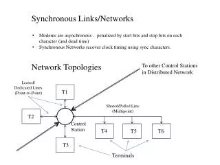
Synchronous Links/Networks. Modems are asynchronous - penalized by start bits and stop bits on each character (and dead time) Synchronous Networks recover clock timing using sync characters. Network Topologies. To other Control Stations in Distributed Network. Leased/ Dedicated Lines

E N D
Synchronous Links/Networks • Modems are asynchronous - penalized by start bits and stop bits on each character (and dead time) • Synchronous Networks recover clock timing using sync characters. Network Topologies To other Control Stations in Distributed Network Leased/ Dedicated Lines (Point-to-Point) T1 Shared/Polled Line (Multipoint) T2 Control Station T4 T5 T6 T3 Terminals
Message Switching and Delivery • Circuit Switching – physical medium is rerouted for duration of message by mechanical switching • Message Switching – “store” entire message when received at control station and “forwarded” to the next control station (or destination terminal) when convenient. • Packet Switching-Message is broken into standard length packets (~1000 bits). Packets are delivered by “store and forward”, and reassembled at receiving terminal. Packets may take different routes and arrive out of order. T1 T2
What are the odds? Message traffic has been observed to obey Poisson (exponential) distribution (kinda . . .) For reception of packets at a node, the probability that exactlyk packets will arrive at a node in t seconds is: Where r is the average arrival rate (packets/second). The probability that K or fewer packets will be received in time t is:
Node Buffer Requirements If a node can transmit an average of m packets per second, then the probability of exactlyc packets being transmitted (service completions) is: If a node, on average, is transmitting as many packets as it is receiving, then its internal packet queue will contain, on average, The average packet delay is If r > m, the buffer will overflow and the node is “blocked”
Synchronous Messaging Protocols • Character/Byte Protocols (e.g. IBM’s BSC/bisync) • Byte Count Protocols – Header contains byte count (DDCMP) • Bit Frame Oriented Protocols (X.25) contain dedicated fields for • Start • Stop • Destination Address • Count • Error check • Data • Message/packet framing • Clock Synchronization • Master/Slave determination • Error detection/Retransmission • Flow Control
Bisync Link Control Characters: ACK: Acknowledge Error-Free reception of Block NACK: Error Detected WACK: Wait for ACK DLE: Link Escape DLE-STX: Binary data (Transparency) mode Poll Multipoint terminals by address Multipoint: Sender responds with ACK when polled Point-to-Point: Sender requests service (ENQ character) • Once Sender is granted use of the line, he sends several SYN (synchronization) characters, • Followed (optionally) by a header block preceded by SOH (Start-of-header), • Followed by one or more text blocks ending with EOB/ETX and Block Check byte • End of Transmission (EOT) terminates the message. ACK … SYN … P-P SYN SOH Header Text message bytes EOB STX BCC ENQ … STX Text message bytes EOB BCC … STX Text message bytes ETX BCC EOT
BOP: X.25 Transmitter must insert a zero after any sequence of five consecutive 1s. Receiver must remove any 0 it sees after five consecutive 1s. Message bits Stop Flag 01111110 Start Flag 01111110 Address Field 8 bits Control Field 8 bits CRC 16 bits Supervisory Frame Control Field Address of sending station Control Code 1 P/F Next Frame # 0 Data Frame Control Field 0 P/F Next Frame # This Frame # Un-Numbered Frame Control Field Control Code 1 P/F Control Code 1