Download
1 / 20
200 likes | 345 Views
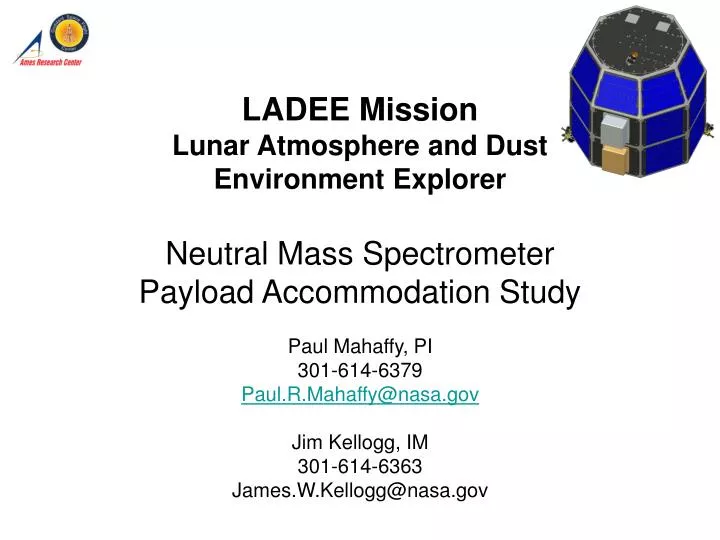
LADEE Mission Lunar Atmosphere and Dust Environment Explorer Neutral Mass Spectrometer Payload Accommodation Study. Paul Mahaffy, PI 301-614-6379 Paul.R.Mahaffy@nasa.gov Jim Kellogg, IM 301-614-6363 James.W.Kellogg@nasa.gov. Instrument Accommodation Review (IAR).

E N D
LADEE MissionLunar Atmosphere and Dust Environment ExplorerNeutral Mass Spectrometer Payload Accommodation Study Paul Mahaffy, PI 301-614-6379 Paul.R.Mahaffy@nasa.gov Jim Kellogg, IM 301-614-6363 James.W.Kellogg@nasa.gov
Instrument Accommodation Review (IAR) 1. Instrument Description 2. Driving Instrument Interfaces • Electrical Power Interface • Command and Data interfaces • Software Interfaces • Mechanical Interfaces (mass & CG) • Thermal Interfaces 3. Instrument FOV Requirements 4. Driving Environmental Interfaces (inc. radiation, contamination, EMI) 5. Driving Operational Requirements • OPS Concept (including instrument modes, etc) • Operational Constraints 6. Programmatic Requirements • Schedule (including payload I&T and System I&T support) 7. Potential Trade Studies:
1. Instrument Description NMS Sensor EM from CONTOUR NGIMS Ion Source Assembly Ion Detector Assembly Analyzer Assembly
8.6” (21.8) 6.8” (17.3 cm) 11.5” * (29.2 cm) 15” (38.1 cm) 1. Instrument Description (cont.) Electronics from SAM and CONTOURdesigns Cassini INMS CONTOUR NGIMS CRAF dual open/closed ion source design adopted for CONTOUR & Cassini mass spectrometers MSL SAM Electronics
2. Driving Instrument Interfaces • Electrical Power Interface • Command and Data interfaces • Software Interfaces • Mechanical Interfaces (mass & CG) • Thermal Interfaces
2a) Electrical Power Interface Pyro Circuit Power: NMS has two, one ohm redundant pyrotechnics fired simultaneously, each requiring 5 amperes for a minimum of 15 milliseconds from the spacecraft.
2b) Command & Data Interfaces (1 of 3) • Detailed description of the RS-422 high speed serial interface provided separately (ref: MSL-336-0314) • NMS Data Generation Rate(s): • Normal science mode: 5 kbs • 100 bps for housekeeping only • NMS data will be packetized • CCSDS headers will not be included in NMS data packets • Extra space needed for packaging data not charged to NMS • No data compression • NMS will send data only when S/C requests for data
2b) Command & Data Interfaces (2 of 3) • C&DH interface command and telemetry • Redundant signals for command and telemetry (Command A, Command B, Telemetry A, Telemetry B) • Each interface consists of differential RS-422 signals (frame, clock, data, ready) • Clock rate is a nominal 2 MHz • Discrete Inputs • Reset or NMI A or B (NMS CPU reset) • NMS current monitor readout • Time Tic Requirements: • Time to the nearest second at power-on or when requested (protocols in FSW)
2b) Command & Data Interfaces (3 of 3) • Communications Protocol • All communications between the S/C and NMS shall be initiated by command from S/C. NMS shall respond to each command with a reply, which will contain status flags and optional telemetry data • Commands and replies shall conform to a common format • Opcode (8 bits) • Flags (24 bits) • Data length (32 bits, may be zero) • Data (variable, number of bytes specified in data length field, omitted when data length is zero) • Checksum (32 bits, Fletcher’s checksum, computed as described in http://en.wikipedia.org/wiki/Fletcher's_checksum).
2c) Software Interfaces (1 of 3) • At power on or hard reset • NMS enters boot mode and remains in boot mode for 30 seconds. • During this time NMS can receive a script, program or table upload by command from S/C • Following a successful program load or the expiration of the boot mode time, NMS enters normal operational mode • In the normal operational mode, S/C shall poll for data approximately every 1 second [TBC]. • NMS shall respond to each such request with a data packet (or an empty reply frame indicating no data to transmit). • The failure of NMS to reply after [TBD] retries shall cause S/C to initiate a hard reset
2c) Software Interfaces (2 of 3) • When NMS enters operational mode it will assert a flag in the status flags field of every reply frame indicating that it has completed its boot-up sequence (called the “boot-up flag.”) • When SC detects the boot-up flag, S/C shall transmit the following command sequence: • Transmit the time sync command to NMS • Transmit any special operational sequence commands requested by NMS ground controllers • Transmit any special parameters or safety commands to NMS as determined by onboard computer or spacecraft operators • The reception of the time sync command shall cause NMS to clear the boot-up flag on all further command replies. • If NMS suffers a severe error or spontaneous reset, it shall reassert the boot-up flag. • This shall alert S/C to the occurrence of the anomalous event, and shall cause the S/C to retransmit the command sequence
2c) Software Interfaces (3 of 3) • The spacecraft shall provide commands to indicate • The start of NMS science sequence • “unsafe” flags if S/C senses TBD anomalous conditions
2d) Mechanical Interfaces NMS CAD model provided to spacecraft team
2e) Thermal Interfaces • NMS thermally isolated from spacecraft structure • NMS manages its own heat rejection using thermal coatings on NMS covers • Survival heater power is TBD • Requirement for survival heaters and temperature sensors is TBD pending further thermal analysis.
3) Instrument FOV Requirements • 2 Pi SR field of view for NMS closed source • View direction is perpendicular to the NMS mounting plate
4. Driving Environmental Interfaces • Loads environments needed by NMS (to be provided by S/C) • Contamination • NMS breakoff cover provides protection during S/C I&T, launch operations and cruise, deployed after lunar orbit insertion • Location of thrusters relative to NMS closed source aperture placed to minimize plume impingement on NMS • Level of allowable SC contamination, TBD • EMI from laser com and RF: Assume NMS off when laser com is on or when data transmission in progress • NMS Radiation Tolerance • Parts selected to meet 20 krad requirement • SEL LET thresholds greater than 75MeV cm2/mg • SEU LET thresholds greater than 37MeV cm2/mg • Software based EDAC
5. Driving Operational Requirements • NMS boresight to be pointed in orbit RAM direction during science observations • NMS turned off during laser com transmission due to if EMI environment
6. Programmatic Requirements • Cost & schedule plan will be included in concept study report • SMEX class D MAR used for NMS • NMS science CoI provision from phase B thru phase E • GSFC SOC planning/cost under direction of payload office • Spacecraft simulator to be provided by Ames
7. Potential Trade Studies • Instrument mounting plate vs. direct mount to sc • Source efficiency trade • Orbit optimization for NMS measurements • Phase F and end of mission operations