Download
1 / 52
520 likes | 665 Views
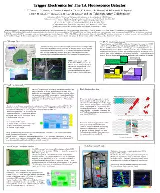
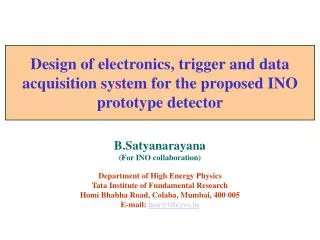
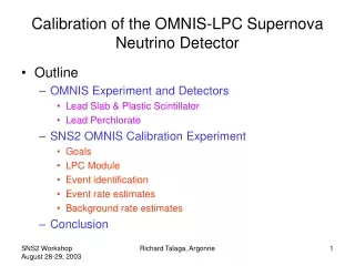
Trigger system for the T600 detector: applications to Supernova detection. G. Fiorillo for the ICARUS Collaboration. CRYODET Workshop LNGS, March 13-14, 2006. Cryostat (half-module). Readout electronics. T600 semimodule. View of the inner detector. ICARUS DAQ. Physics considerations.

E N D
Trigger system for the T600 detector: applications to Supernova detection G. Fiorillo for the ICARUS Collaboration CRYODET Workshop LNGS, March 13-14, 2006
Cryostat (half-module) Readout electronics T600 semimodule View of the inner detector Cryodet Workshop, LNGS 13 March 2006
ICARUS DAQ Cryodet Workshop, LNGS 13 March 2006
Physics considerations • Events in T600 at LNGS: • Cosmic rays muons • Atmospheric neutrinos • Solar neutrinos + neutrons E ~ 5 MeV • Neutrinos from Supernova (burst) E ~ 20 MeV • Proton decay • CNGS neutrinos external timing • Beam muons Cryodet Workshop, LNGS 13 March 2006
Event topologies Muon Cosmic-ray shower Low energy electrons Cryodet Workshop, LNGS 13 March 2006
Data volume (A. Rubbia ICARUS IM Sept.02) • 1.5 m drift or 1 ms is 2500 samples of 400 ns • 27130 wires with 2500 drift samples • 32 wires per board x 18 boards per crate x 48 crates= 27648 readout channels of 2500 samples Total volume: 260 TB per year (25% CMS or ATLAS experiment!) Volumes are dominated by physics backgrounds: neutron capture and muon crossing Cryodet Workshop, LNGS 13 March 2006
low energy reactions in Argon • Elastic scattering from neutrinos (ES) • Electron-neutrino absorption (CC) • Elastic scattering from antineutrinos (ES) • Electron-antineutrino absorption (CC) f(ne)+0.15 f(nm + nt) f(ne) Q=5.885 MeV f(ne)+0.34 f(nm + nt) f(ne) Q≈8 MeV Neutrinos from Supernovae Cryodet Workshop, LNGS 13 March 2006
Shock breakout collapse Expected events from SN at 10 kpc in 3 kton No oscillation Oscillation Non adiabatic Adiabatic reaction Elastic 41 41 27 absorption 203 995 730 TOTAL 244 1036 757 A.Rubbia, I.Gil-Botella Cryodet Workshop, LNGS 13 March 2006
Supernova burst • Specific time structure • Ex.: ~ 100 SN triggers in T300 in 1 sec (expected for a SN at 10 kpc, with an energy release of 1053 erg) • Global trigger (full detector readout): bandwidth + storage problem • 1 event = 27648 ch 2500 samples 2 bytes ~ 130 MB 13 GB total • DAQ throughput limit: < 40 MBytes/s (or >5 minutes to empty buffers) • Local trigger: SN events are localized and limited to 1 crate per view • 5 events per crate (on average) in COLL + IND2 views ~ 40 MB/crate • 13 events per crate (on average) in IND1 view ~ 60 MB/crate Each crate can be read-out as a separate event Cryodet Workshop, LNGS 13 March 2006
Segmented trigger • Intrinsic granularity of the trigger is a crate • The requirement of the Supernova trigger introduces two types of triggers • Global triggers: an entire T300 is readout as a single event • Local triggers: the various crates are readout independently as separate events • Overlapping in time local triggers can be reconstructed offline (or online) using the absolute time information • The implementation of local triggers presupposes the development of a small “local trigger control unit” card in each crate Cryodet Workshop, LNGS 13 March 2006
Segmented trigger pixel definition T600 Half Module – 1 chamber viewed from cathode Rack 13 Rack 11 Rack 20 Rack 1 864 mm 32 x 9 Induction II wires 32 x 9 Collection wires 1 pixel area: ~ 0.6 m2 Total Number of Pixels ~ 80 Cryodet Workshop, LNGS 13 March 2006
MC simulation: low energy events ICAFLUKA Cryodet Workshop, LNGS 13 March 2006
MC simulation: high energy events ICAFLUKA Cryodet Workshop, LNGS 13 March 2006
Preliminary considerations • Trigger rate is dominated by physics background • Neutron capture rates expected in T600 (ICARUS/TM-2002/13): • 210-4 s-1 from natural radioactivity of the rock • 0.030.1 s-1from Al container • Segmented trigger potentially solves bandwidth and storage problems • Event pre-classification data streams • extraction of solar neutrino data from low energy stream • Test bed for larger LAr detector low energy trigger Cryodet Workshop, LNGS 13 March 2006
Trigger Input • PMTs (global and local triggers) • DAEDALUS (Based on single wire information) • AWS (Analog 32 wires sum, exists on the front-panel of each analogue card, local triggers) • External (beam profile chambers, cern-spill, …global) Cryodet Workshop, LNGS 13 March 2006
[x 50 ns] PMT system PMT signal The high light yield measured in T600 provides the natural solution for T0 definition and (in part) for trigger Cryodet Workshop, LNGS 13 March 2006
A PMT based trigger • The PMT system allows for the design of a fast triggering system able to select the events on the basis of the scintillation light produced in liquid argon. • The study is based on the MC simulation of real events inside the T600 detector. • The contribution due to the dark counts and noise is taken into account. • The segmentation of the sensitive volume according to the PMT layout permits the definition of local triggers. Cryodet Workshop, LNGS 13 March 2006
Trigger Efficiency Plots The plot summarizes the trigger efficiency (triples case) as a function of the electron kinetic energy, for different threshold values (G.Raselli IM Jan06). Cryodet Workshop, LNGS 13 March 2006
0.5 1 1.5 2 3 3 5 7 10 15 Trigger Efficiency Tables Trigger efficiency/Stochastic rate (triples case) Threshold (phe) Energy (MeV) 98.3% 95.2% 86.1% 73.6% 46.2% 6.2 Hz 1.1 Hz 0.2 Hz <0.1 Hz «0.1 Hz 99.7% 99.1% 97.1% 93.3% 80.2% 6.2 Hz 1.1 Hz 0.2 Hz <0.1 Hz «0.1 Hz 99.9% 99.8% 99.1% 97.9% 92.8% 6.2 Hz 1.1 Hz 0.2 Hz <0.1 Hz «0.1 Hz 99.9% 99.9% 99.8% 99.4% 97.9% 6.2 Hz 1.1 Hz 0.2 Hz <0.1 Hz «0.1 Hz 99.9% 99.9% 99.9% 99.9% 99.6% 6.2 Hz 1.1 Hz 0.2 Hz <0.1 Hz «0.1 Hz Cryodet Workshop, LNGS 13 March 2006
Basic design requirements • Redundancy important to measure efficiency • Global trigger: • Generated by PMTs or external • drift deadtime GLOBAL_DRIFT (1ms) • Read-out deadtime GLOBAL_BUSY (1s) vetoes new global triggers • Local triggers vetoed during GLOBAL_DRIFT • Local trigger: • Generated by AWS + PMT • LOCAL_DRIFT (1ms) vetoes new local triggers Cryodet Workshop, LNGS 13 March 2006
Trigger System Architecture • LTCU: discriminates the inputs, has one independent threshold for each input, gives 1st level trigger proposals as output; • TCU: performs coincidences between LTCUs proposals, processes the fired pixels to study and label the event topology, produces global or local trigger proposals; • Trigger Supervisor: monitoring of the trigger and the DAQ system, statistical functions. Cryodet Workshop, LNGS 13 March 2006
CERN or any other external request T11 9 TRIGGER SUPERVISOR from v791 T120 DAQ LTCU TCU T21 9 n-bit request T220 96 Trigger Distribution 20 boards per chamber (80 boards for T600) v816 PMT LTCU 4 boards per T600 Trigger System Architecture Cryodet Workshop, LNGS 13 March 2006
T1 9 from v791 LTCU T2 9 1st trigger level: LTCU • 1 board per crate - 20 boards per chamber • each board receives as input 9 + 9 coming from the v791 analog boards (generally 9 of 2nd induction and 9 of collection) TCU • LTCU discriminates the 18 inputs comparing them with remotely controlled thresholds. Noisy inputs can be masked • Gives as output two separate trigger proposals (T1 and T2), corresponding to the OR of INDII or COLL boards respectively • Test mode to check the working status • Counting capabilities to check rates of trigger proposals for each input • Board functionalities are driven by a remote controller Cryodet Workshop, LNGS 13 March 2006
CERN or any other external request AWS LTCU T11 TS T120 TCU T21 n-bit request T220 PMT LTCU 2nd trigger level: TCU • 1 board per chamber • VME standard • each board receives as input 40 signals from the AWS LTCUs (2 T signals x 20 boards) and N signals from PMT LTCU • TCU performs coincidences between: • the wire planes (in a ~3 ms time window), • the PMT signals, • the external requests • checks Majority, Minority, 2D Pattern logic conditions • event is labelled according to topology • An n-bit-word trigger request is sent to the Trigger Supervisor, defining the fired crates Cryodet Workshop, LNGS 13 March 2006
Trigger Supervisor • 1 or more boards • VME standard • TS receives 4 input n-bit-words from the TCU and the ABS CLOCK • TS evaluates if the trigger request from TCUcorresponds to a Local Trigger or a Global Trigger ABS CLOCK TCU n-bit request TRIGGER SUPERVISOR DAQ 96 Trigger Distribution v816 • Monitoring of the system and validation of Trigger requests. • GLOBAL/LOCAL DRIFT/BUSY Logic • Trigger signal distribution to the v816 • Event trigger tag (trigger number, time, type, acquisition dead time…) • Statistics for the trigger system Cryodet Workshop, LNGS 13 March 2006
TS GLOBAL/LOCAL Logic • Trigger classification depends on: • Energy deposition/number of PMT fired. • Detector occupancy • 2D/3D Pattern of fired pixels • TS gives GLOBAL trigger when a MAJORITY condition is met in PMT logic • Otherwise the trigger is LOCAL Cryodet Workshop, LNGS 13 March 2006
The trigger generation algorithm Cryodet Workshop, LNGS 13 March 2006
PMT Induction IISsignal CollectionSsignal LTCU T1 signal LTCU T2 signal DT 3 ms TCU Trigger request n-bit TS Trigger signal Trigger dead time DT 1.5 ms Time Diagram Cryodet Workshop, LNGS 13 March 2006
The LTCU prototype v1.0 VDAC IN Voltage follower IN OUT Discriminator RC filter Power supply FPGA Input stage DAC 10 MHz oscillator Trigger outputs 18 inputs RS232 interface Cryodet Workshop, LNGS 13 March 2006
INPUT STAGE Xilinx Spartan XC2S100 SYNCHRONOUS FIFO IDT72V263 VME INTERFACE Xilinx Spartan XC2S100 80 programmable input / output 2nd level Prototype TCU Cryodet Workshop, LNGS 13 March 2006
Summary • The readout of SN events, due to their burst nature, requires the implementation of local triggersto overcome data volume problems • The segmentation of the sensitive volume permits the definition of local triggers potentially solving bandwidth and storage problems • Event pre-classification by the trigger allows for the definition of data streams (useful for the analysis) • Redundancy in the trigger system is important in order to measure the efficiencies • Segmented Trigger architecture based on PMTs and Wires • Global trigger: the full detector is read-out as a single event • Local trigger: only active “pixels” are read-out as separate events • Events are labelled according to pixel topology Cryodet Workshop, LNGS 13 March 2006
LTCU prototype for AWSv1.0 Cryodet Workshop, LNGS 13 March 2006
LTCU v1.0 Cryodet Workshop, LNGS 13 March 2006
The LTCU functionalities v1.8i • Mask the input channels; • Read the mask status; • Set the thresholds; • Monitor the trigger rate for each input; • Discriminator test mode; • Select one discriminator output put on front panel. All the board functionalities are remotely controlled via RS232 interface. Cryodet Workshop, LNGS 13 March 2006
V1.0 test on 50 liters LAr TPC Cryodet Workshop, LNGS 13 March 2006
Trigger rate test chain V789 V816 • LTCU inputs = 4 S signals from collection plane; • Trigger generated from only one S input (no FastOR); • LTCU trigger output distributed to V816 module. IN trigger IN IN IN IN IN IN IN IN V791 Ind Coll LTCU OUT OUT OUT OUT OUT OUT OUT OUT OUT S S S S LTCU Trigger OUT IN PC (RS232) Analog S OUT Cryodet Workshop, LNGS 13 March 2006
Trigger Rate Plateau (I) Plateau zones Cryodet Workshop, LNGS 13 March 2006
Trigger Rate Plateau (II) Plateau zones Cryodet Workshop, LNGS 13 March 2006
Trigger efficiency test chain V789 V816 • LTCU inputs = 4 S signals from collection plane; • One LTCU IN and Trigger OUT digitalized by a modified V791; • PMT trigger distributed to V816 module. IN trigger PMT IN IN IN IN IN IN IN IN Modified V791 V791 Ind Coll LTCU OUT OUT OUT OUT OUT OUT OUT OUT OUT OUT S S S S IN IN IN PC (RS232) Analog S OUT Cryodet Workshop, LNGS 13 March 2006
Test Results Cryodet Workshop, LNGS 13 March 2006
LTCU prototype v2.0 VTH VTest VREF or IN VTH IN VREF Band-pass filter Selectable inverter (G=1) DAC (for one channel) OUT Filter for low noise performance Input stage (for one channel) Power supply an filter Stable 259mV tension circuit VREF for DAC EM/RF Screening for input stage Cryodet Workshop, LNGS 13 March 2006
PWR and GND distribution for LTCU v2.0 Four GND and two PWR planes VCC, DGND (V791 digital stage) +5A1,AGND1 (V791 mux stage) ±5A,AGND (V791 preamp. stage) Cryodet Workshop, LNGS 13 March 2006
The second trigger level Trigger Control Unit Preliminary design
TCU Features • ≥1 boards per chamber (depending on segmentation) • VME standard • checks Majority, 2D/3D Pattern logic conditions • event is labelled according to topology • Each TCU module receives as input • Naws signals from the 20 AWS-LTCU boards of a chamber • Npmt signals from PMT-LTCU • Next from external (spectrometers, beam, ...) • TCU performs coincidences between: • The wire planes (in a 3ms time windows) • PMT signals • External requests Cryodet Workshop, LNGS 13 March 2006
Pattern Recognition Need to store the evolution in time of the number of fired pixel A long track fires consecutive pixels (at different times) according to direction. In this case the event is global can be acquired as many local events. In case of a Supernova burst several pixels could be fired with a big spacing in position and in time. Cryodet Workshop, LNGS 13 March 2006
General Idea on Partial majority Rack 13 Rack 11 • Window runs over the detector • Majority condition is checked for each window Cryodet Workshop, LNGS 13 March 2006
General scheme of TCU Cryodet Workshop, LNGS 13 March 2006
WiRe coincidences FPGA Features • The detector is subdivided in four sections • Each section is monitored by a different WR-FPGA • Each WR-FPGA • Makes coincidences between wires of different directions • Checks the occupancy of the section • Detects spots, tracks. Cryodet Workshop, LNGS 13 March 2006
PMT FPGA Features • receives an N bit Word which defines PMT status • makes concidences between PMT and wires • makes global trigger proposals VME interface Features Directly interfaced to VME CPU. Establishes communication between VME and the rest of the board. Cryodet Workshop, LNGS 13 March 2006
Wire CoincidencesFPGApreliminary PIPELINE A0_B[4:0] 9 SYNC BLK AND BLK AA INA A1_B[5:1] A2_B[6:2] 9 MASK 9 A3_B[7:3] ENC A4_B[8:4] FLASH A5_B[9:5] 13 SYNC BLK BB A6_B[10:6] MASK A7_B[11:7] 13 13 INB Internal Xilinx Memory A8_B[12:8] MJLOCAL FLASH ADDRESS GENERATOR ADR[4:0] CLK REG_C SUM BLK ENCA2 Whole Carpet Majority REG_B MJGLOBAL ENCA3 VTH REG_A Cryodet Workshop, LNGS 13 March 2006 ENCA