Download
1 / 1
10 likes | 131 Views
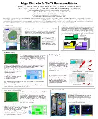
SDF. 1 telescope. Signal 16ch x16. Hit Pattern. Final Trigger. S ignal D igitizer and F inder module converts the analogue signals to digital signals 1st level Trigger the wave form recognition of the fluorescence. T rack F inder module accumulates the result of the 16 SDF

E N D
SDF 1 telescope Signal 16ch x16 Hit Pattern Final Trigger Signal Digitizer and Finder module converts the analogue signals to digital signals 1st level Trigger the wave form recognition of the fluorescence Track Finder module accumulates the result of the 16 SDF synchronizes the timing of all SDF modules 2ndlevel Trigger decides whether hit pattern is the track or not TF CTD Trigger Electronics for The TA Fluorescence Detector Y. Tamedaa, J. D. Smithb, M. Tanakac, S. Ogiod, A. Taketae, K. Kadotao, S.B. Thomasb, M. Fukushimae, H. Sagawae, S. Udoe, M. Takedae, T. Matsudac, K. Hiyamae, H. Tokunoe and the Telescope Array Collaboration (a) Graduate School of Science and Engineering, Tokyo Institute of Technology, Tokyo 152-8550, Japan (b) Department of Physics and High Energy Astrophysics Institute, University of Utah, Salt Lake City, Utah, USA (c) Institute of Particle and Nuclear Studies, KEK, Tsukuba 305-0801, Japan (d) Graduate School of Science, Osaka City University, Osaka 558-8585, Japan (e) Institute for Cosmic Ray Research, University of Tokyo, Kashiwa 277-8582, Japan (f) Faculty of Engineering, Musashi Institute of Technology, Tokyo 158-8557, Japan In this presentation, we introduce a triggering system developed for the TA fluorescence detectors. The system consists of two types of VME 9U modules, i.e., a Track Finder (TF) module for each telescope and a Central Trigger Distributor (CTD) module which controls 12 cameras in each station. In a cycle of event recognition, a) SDF (Signal Digitizer and Finder) modules carry out fluorescence signal recognitions for each PMT and the results are transferred to TF. b) The main task of TF is to recognize tracks in a camera image, and it sends the result to CTD. c) The CTD module accumulates the results from all the TF modules in a station, and gives a final decision, which is sent back to all the TF modules to trigger the data acquisition processes. The CTD module generates a master clock to synchronize all the electronics, and has a GPS for recording the absolute vent time. Telescope Array TA FD Electronics diagram A Signal Digitizer and Finder(SDF) module has 16ch input. One camera has 16 SDF modules. It records PMT output with digitizing with 12bit 40 MHz FADC and it makes a 16x16 size map of 0/1(the 1st level trigger ) for each 12.8 µs interval, and they transferred this map to the Track Finder(TF) module. The TF module searches air shower fluorescence tracks on the map, and the resultant 2nd level trigger code is sent to Central Trigger Distributor(CTD) module. Finally the CTD module decides to generate the event trigger and distribute the final trigger code for all the TF modules. The Telescope Array fluorescence detectors(FD) measure fluorescence light of N2 molecules along with air showers.There will be three FD stations and the distance between each station is about 40 km. In each station there are twelve telescopes, each of which has a spherical mirror optics and a PMT camera system. The spherical mirror optics with a diameter of 3.3 m consists of 18 segment mirrors. FD station 2nd level Trigger Code Central Trigger Distributor module sends out the clock for all SDF and TF collects the 2nd level triggers Final Trigger decides whether to start data taking SD Array A PMT camera system has 256 PMTs, and each PMT is viewing 1o x 1osky. In total the field of view of one telescope is equivalent to 18o x15.6o. The sensitivity of FD electronics enables for us to detect shower tracks of dozens of km apart. PMT camera Clock, Frame ID Final Trigger 3.3m Telescope Mirror FD station Track Finder module Track finding algorithm One TF is assigned to one telescope. It is mounted on a VME crate, and it is connected to 16 SDF modules through the VME back planes. Also it is connected to CTD via external twisted pair cables. One important role of TF is transferring the system clock which is synthesized by CTD, to SDF for synchronization of all the modules. All the logics for the track finding are written on a FPGA, Xilinx Spartan 2E. TF send the 2nd level trigger code=1 when it finds a complete track by comparing each 144 sub matrices of 256ch hit pattern with 5x5 trigger pattern matrices. A complete track is an image of at least 5 adjoining PMTs. The processing time for finding a complete track is 144 x 25 ns. The trigger pattern is 5 or more PMTs adjoining and all 2255x5 sub matrix patterns are memorized in static RAMs(512 x 8 KB). Results of 1st level trigger are transferred as a hit pattern of 256 bits plus a non conditional(NC) bit. The NC bit is set when a significantly large signal is found on at least one PMT, for example, in the case of measurement of Xe flasher, or of the signal induced by muon hit on a PMT, etc. When the hit pattern and a NC bit satisfies the triggering conditions, TF generates a 2nd level trigger and sends the 2nd level trigger code to CTD.This trigger codes are • Complete Track is found. • Partial Track is found at the camera edge. • Non conditional bit is transferred. • External Trigger is input. TF send the 2nd level trigger code=2 when it finds a partial track at the boarder of the camera by comparing 4X4 sub matrix along the edge of camera with trigger patterns. In this case, the trigger pattern is 3 or more PMTs adjoining at the edge. These patterns are also memorized in one static RAM. Finally, TF transfers the 2nd level trigger code and a frame ID. The frame ID is an identification number labeled to every waveform data of 12.8µs. When TF receives a final trigger pulse and a frame ID from CTD, it distributes trigger pulses for all the SDFs mounted on the same crate through a back plane, to prepare a data acquisition process. In parallel, TF stores the triggered frame ID and sends IRQ to the VME control PC. Test observation @ Utah Central Trigger Distributor module One CTD is assigned one station, and it communicated with 12 TF module, i.e., all TF in the station. CTD has two main roles programed in FPGA(Xilinx Spartan 2E). One role is to generate and distribute the system clock of all the electronics modules. CTD supplies 40MHz clock and the reset signal distributed to TFs, and through TF, to 16 x 12 SDFs. Additionally, a GPS receiver module(Motorola M12+) is installed, so that CTD can record an absolute time for each trigger with an accuracy of ±a few ns. This information is important for coincidences with other station’s triggers and the surface array triggers. The first test observation was performed in June, 2005 at Black Rock Mesa(Utah). We obtained data of Xe flasher signals and YAP signals, for checking the adjusting procedure for HV power supplies. We flashed a 64 ch LED matrix light source making virtual air shower tracks to confirm the trigger logic rum correctly. The set of one telescope with electronics run successfully. We observed some fluorescence like events. TF SDF The other main role is the final decision for data acquisitions. CTD accumulates the 2nd level trigger code from TFs every 12.8 µs. If one of the 2nd level trigger codes is equal to an external trigger, a NC trigger or a complete track trigger, CTD generates a final trigger. On the other hand, when CTD receives the 2nd level trigger code of a partial track from two adjacent TFs, a final trigger is also generated. In both cases, CTD sends a trigger pulse to all the TF, and sends IRQ to CTD control PC. HV