Download
1 / 23
230 likes | 345 Views
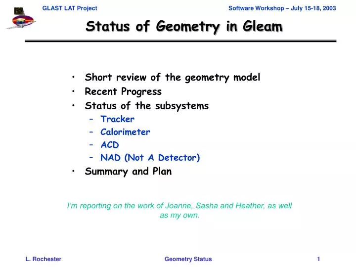
Status of Geometry in Gleam. Short review of the geometry model Recent Progress Status of the subsystems Tracker Calorimeter ACD NAD (Not A Detector) Summary and Plan. I’m reporting on the work of Joanne, Sasha and Heather, as well as my own. Introduction to xmlGeoDbs.

E N D
Status of Geometry in Gleam • Short review of the geometry model • Recent Progress • Status of the subsystems • Tracker • Calorimeter • ACD • NAD (Not A Detector) • Summary and Plan I’m reporting on the work of Joanne, Sasha and Heather, as well as my own.
Introduction to xmlGeoDbs • Primary constants • material names • integer constants (counts) • floating point constants (dimensions, offsets) • Derived constants (mostly offsets) • From primary constants using xml arithmetic • Construction of volumes • Dimensions and offsets are all primary or derived constants • No hardwired numbers! (except for “2”, and “90”) • Identifiers – not of interest here For a nice description see: GLAST software page->Software Cantons->Geometry->Writing XML Files for GLAST
Description of LAT and Subsystems The overall description of the LAT can be found in: • xmlGeoDbs/xml/flight/flightSegVols.xml Subsystem volumes are defined in: • xmlGeoDbs/xml/flight/flightTKROneTkr.xml • xmlGeoDbs/xml/flight/flightCALOneCal(SegVols).xml • xmlGeoDbs/xml/flight/flightACDAcd.xml • xmlGeoDbs/xml/flight/flightNADGeo.xml
Building the geometry • Define primitive (uniform material, simple shape) volumes • Boxes • Cylinders • Assemble into stacks along an axis or • Position individually in a composition volume. • Compositions always have an explicit envelope volume; stacks never do. • May have arbitrary levels of nesting. • Dimensions and offsets appearing in the source volume descriptions are always referred to by name as previously-defined primary or derived constants.
Example Volume: Tracker Closeout Side Primitive volume (box). Has a name, material and dimensions. May also be marked as sensitive. <box name="TKRCloseoutRegLong" XREF="TKRCloseoutLen" YREF="TKRCloseoutWidth" ZREF="TKRCloseoutThick" materialREF="TKRCloseoutMat“ />
Example Volume: Tracker Tray Stack along z-axis. Since components are immediately adjacent and are all centered in transverse dimensions, no offsets are required. <stackZ name="trayBot" > <axisPos volume="TKRFaceMin" > <idField name="fTKRTrayCmp" valueREF="eTKRBotFace" /> </axisPos> <axisPos volume="TKRCoreOuterBottom" > <idField name="fTKRTrayCmp" valueREF="eTKRCoreClose" /> </axisPos> <axisPos volume="TKRTopFaceReg" > <idField name="fTKRTrayCmp" valueREF="eTKRTopFace" /> </axisPos> <axisPos volume="SiLayerYMeas" > <idField name="fTKRTrayCmp" valueREF="eTKRSiTop" /> </axisPos> </stackZ> Note: xml doesn’t know height of stack after it’s done making it…
Example Volume: Closeout Assembly Composition of Tracker core+closeout+MCM boards. (Core is centered, needs no offsets.) <composition name="TKRCoreReg" envelope="TKRCoreRegEnv"> <posXYZ volume="TKRCoreRegBox"> <idField name="fBorderCmp" value="eCenter" /> </posXYZ> <posXYZ volume="TKRCloseoutRegLong" YREF="TKRCloseout_dt"> <idField name="fBorderCmp" value="eTop" /> </posXYZ> <posXYZ volume="TKRCloseoutRegLong" YREF="TKRCloseout_dtn"> <idField name="fBorderCmp" valueREF="eBottom" /> .... (more closeout pieces go here) <posXYZ volume="TKRMCM" YREF="TKRMCM_dtn" ZREF="TKRMCMint_dzn" > <idField name="fBorderCmp" valueREF="eFarBottom" /> </posXYZ> <posXYZ volume="TKRMCM" YREF="TKRMCM_dt" ZREF="TKRMCMint_dz"> <idField name="fBorderCmp" valueREF="eFarTop" /> </posXYZ> </composition>
Recent Progress In preparation for DC1, we’ve conducted reviews of the Gleam geometry for the tracker and calorimeter. ACD will follow. See: http://www-glast.slac.stanford.edu/software/CAL/GeometryReview_agenda.htm and http://www-glast.slac.stanford.edu/software/TKR/TKRGeometryReview_agenda.htm The purpose of the reviews was to refocus attention on the geometry: • to review and verify the implementation • to catch up with design changes since the last iteration • to look for places where the model can be improved • to improve the way the design (and design changes) are communicated to the software developers. Many of necessary changes have already been implemented.
Updates to Tracker Geometry Bugs Fixed • Z=0 was at bottom of grid, rather than at top • Would make no difference if code were translationally invariant • But it did! After removing lots of hard-wired constants, seems to be better… • Standard test almost ready • Wrong converter • SuperGlast converter was changed from pure W to W alloy • Thickness was increased to get back to 18% r.l. • Model had a thicker pure tungsten converter • Offset • Tracker was centered in stay-clear, instead of sitting on grid Design changes • Bottom tray reworked • Dimensions (thicker face plates, thicker overall) • Materials (light core changed to heavy)
Before and After Previous New
Summary of “Active” Radiation Lengths • W Converter 1.0850 • Silicon 0.1584 • Core 0.0563 • BotFace 0.0258 • TopFace 0.0453 • BotBias 0.0250 • Total 1.3958 • Top 3 items are simple elements; 93% of r.l.so “Nothing can go wrong!” • Remaining 3 are composites; mostly ~carbon, with some Si, Cu, etc.
Radiation Lengths for some common Materials H Polystyrene C Kapton, Mylar O G10 Al Si Fe Cu CsI W
Passive Tracker – To Do • Walls: includes carbon fiber, bolts • needs Al coating • MCM: mass calculation based on BTEM module • Should be redone, when we get better info • Closeout • Complicated shape; dimensions and effective density should be reviewed. • Top/Bottom tray • More accurate model of frame, especially bottom • Other material not in model • Cables • Flexures • Reality check: compare weight of tracker in Geometry with design • Heat straps • ???
CsI crystal Top frame (Al) Carbon fiber structure Crystal wrap (VM2000) Closeout plate (Al) Side panel (Al) PCB Base plate (Al) Cylindrical support (Al) CAL geometry overview(not to scale – only 8 crystals per layer shown)
Changes to Gleam Geometry • Done • Position CAL against bottom of grid • Shorten CsI crystals, as per new design (sigh!) • Add individual crystal wraps (placeholder material) • Refine model of top frame • Add sidewalls (placeholder material) • Will probably change crack corrections for ~normal particles • To Do • Add detailed base • Add cylindrical supports
CAL Geometry Updates CAL touches Grid Frame Wrap Walls
The ACD model and SolidView The whole ACD geometry is available in sfx files viewable using SolidView. SolidView allows interaction with a 3D model. SolidView provides an easy mechanism to obtain all of the details concerning the ACD geometry http://www.solidview.com
Updating the ACD Geometry(Lots of little pieces!) First pass – in progress Second pass – late August Update tile and ribbons/fibers dimensions Update tile shell assembly (TSA) support structure dimensions and materials Add Base Electronic Assembly (BEA) support structure Account for mass in fiber cables mounted on the TSA Update thermal blanket Account for mass in the fully populated BEA and electronics chassis assembly.
N (ot) A D(etector) This “subsytem” has become a bit of an orphan. Its geometry description is currently fairly crude. We hope to remedy this soon. Everything else…
Status and Plan: Summary • A number of bugs have been found and fixed in the geometry description, design changes have been applied, and some elements have been refined. The changes are being made roughly in the order of importance. • We expect all the remaining changes to be made by the end of August, based on communications with the relevant people, scrutiny of the relevant documents, etc. • Rich Bielawski of Systems Engineering will be compiling a document capturing the numbers (dimensions and materials) in xmlGeoDbs, with a trace to where they came from. This will include the spacecraft. The subsystem managers will then sign off on these numbers. This should also be done by some time in August.