Download

1 / 48
580 likes | 941 Views
PROPELLER SYSTEM. 1 st - Look at how lift is generated. Then see how it applies to propellers. How lift is generated. PROPELLER SYSTEM. In this direction. Pressure Decreases here. Pressure Remains Constant here. In this example. The result is LIFT. How lift is generated.

E N D
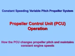
PROPELLER SYSTEM 1st - Look at how lift is generated Then see how it applies to propellers
How lift is generated PROPELLER SYSTEM
In this direction Pressure Decreases here Pressure Remains Constant here In this example The result is LIFT How lift is generated PROPELLER SYSTEM
The result is MORE LIFT Greater Pressure Decrease here Small Pressure Increase here How lift is increased PROPELLER SYSTEM
Direction of travel Aerofoil incline The difference in direction of travel and aerofoil incline is called:- The ANGLE of ATTACK How lift is increased PROPELLER SYSTEM
How does lift apply to PROPELLORS? On Propellers, LIFT is called THRUST And propeller Blades work the same way as aircraft wings When a propeller spins and the aircraft moves forward, the tips of the propeller blades move in a ‘corkscrew’ path This path is called a HELIX PROPELLER SYSTEM
How the blade tip travel produces the HELIX ANGLE PROPELLER SYSTEM
How the blade tip travel produces the HELIX ANGLE PROPELLER SYSTEM
How the blade tip travel produces the HELIX ANGLE PROPELLER SYSTEM
How the blade tip travel produces the HELIX ANGLE PROPELLER SYSTEM
How the blade tip travel produces the HELIX ANGLE PROPELLER SYSTEM
How the blade tip travel produces the HELIX ANGLE PROPELLER SYSTEM
How the blade tip travel produces the HELIX ANGLE PROPELLER SYSTEM
How the blade tip travel produces the HELIX ANGLE PROPELLER SYSTEM
How the blade tip travel produces the HELIX ANGLE PROPELLER SYSTEM
How the blade tip travel produces the HELIX ANGLE PROPELLER SYSTEM
How the blade tip travel produces the HELIX ANGLE PROPELLER SYSTEM
How the blade tip travel produces the HELIX ANGLE PROPELLER SYSTEM
How the blade tip travel produces the HELIX ANGLE PROPELLER SYSTEM
How the blade tip travel produces the HELIX ANGLE PROPELLER SYSTEM
How the blade tip travel produces the HELIX ANGLE PROPELLER SYSTEM
How the blade tip travel produces the HELIX ANGLE PROPELLER SYSTEM
How the blade tip travel produces the HELIX ANGLE PROPELLER SYSTEM
How the blade tip travel produces the HELIX ANGLE PROPELLER SYSTEM
How the blade tip travel produces the HELIX ANGLE PROPELLER SYSTEM
How the blade tip travel produces the HELIX ANGLE PROPELLER SYSTEM
Rotation - Number of Rotations per Minute Forward Speed - Distance Travelled over One Minute How the blade tip travel produces the HELIX ANGLE PROPELLER SYSTEM
RPM Forward Speed How the blade tip travel produces the HELIX ANGLE PROPELLER SYSTEM
RPM Forward Speed How the blade tip travel produces the HELIX ANGLE PROPELLER SYSTEM
RPM Forward Speed How the blade tip travel produces the HELIX ANGLE PROPELLER SYSTEM
RPM Forward Speed How the blade tip travel produces the HELIX ANGLE PROPELLER SYSTEM
RPM Forward Speed How the blade tip travel produces the HELIX ANGLE PROPELLER SYSTEM
RPM Forward Speed How the blade tip travel produces the HELIX ANGLE PROPELLER SYSTEM
RPM Forward Speed How the blade tip travel produces the HELIX ANGLE PROPELLER SYSTEM
How the HELIX ANGLE is changed by engine rpm and forward speed
RPM Faster RPM Forward Speed Changes in FORWARD SPEED and RPM will change the Helix Angle How an increase in RPM changes the Helix Angle How the blade tip travel produces the HELIX ANGLE PROPELLER SYSTEM
RPM RPM Forward Speed Faster Forward Speed Changes in FORWARD SPEED and RPM will change the Helix Angle How an increase in FORWARD SPEED changes the HELIX ANGLE PROPELLER SYSTEM
This is the Helix Angle This is the Angle of Attack Direction of rotation Direction of blade through the air with forward speed Let’s take a closer look at the blade aerofoil and the Helix Angle and thrust (lift) generation If the Helix Angle changes, then we need to change the blade angle. Remember (from the comparison with the aircraft wing), the optimum Angle of Attack is required to maintain most efficient thrust generation. PROPELLER SYSTEM
Sliding Piston Actuating Lever Propeller Blade Direction of Rotation Direction of Flight Actuating Link Hard Stops Fine Pitch Coarse Pitch All propeller blades are actuated by the same mechanical linkage PROPELLER SYSTEM
Coarse pitch Or ‘Feathered’ Fine pitch Direction Of Rotation Maximum resistance to forward speed Minimum resistance to forward speed Maximum resistance to rotation Minimum resistance to rotation Pistontravels between ‘hard’ stops At this hard stop the blade is in this position At this hard stop the blade is in this position The blade angle changes through 90deg with piston travel Note: - blade angle is relative to piston travel PROPELLER SYSTEM
Fine pitch Maximum resistance to forward speed In-flight engine failure – loss of control and Minimum resistance to rotation engine disintegration Zero pitch – or Ground Fine Pitch Good for:- Easier Starting of engine Running engine with no/minimal thrust Direction of Rotation High drag – braking effect on ground Bad for:- In-flight – loss of control Direction of travel Importance of set blade angle PROPELLER SYSTEM
Maximum resistance to rotation Maximum pitch – or Feathered Minimum resistance to forward speed Bad for:- Starting of engine Could cause engine burn-out if running Direction of Rotation Low drag – NO braking effect on ground Good for:- In-flight – loss of control In-flight engine failure – control maintained and engine stops rotating minimizing damage Direction of travel Importance of set blade angle PROPELLER SYSTEM
Reverse Pitch Used for:- High drag – high braking effect on ground Air pushed forward giving reverse thrust Direction of Rotation Usually for military aircraft only Minimal resistance to rotation Bad for:- In-flight – loss of forward speed, aircraft stalls In-flight engine failure – loss of control and reverse rotation increasing engine disintegration Direction of travel Importance of set blade angle PROPELLER SYSTEM
Flight Fine pitch Used for:- Low drag on final approach Used for:- Cruise pitch In-flight descent – faster forward speed than final approach Flight Fine and Cruise Pitch Direction of Rotation Both give minimal drag at low power settings Direction of travel Importance of set blade angle PROPELLER SYSTEM
MID-SPAN ROOT TIP COARSE ANGLE MEDIUM ANGLE FINE ANGLE Typical Blade Typical 3 Blade Prop BLADE ANGLE RELATIVE TO DISTANCE (AND THEREFORE SPEED) TRAVELLED BY ROOT, MID-SPAN AND TIP DISTANCE TRAVELLED BY ROOT, MID-SPAN AND TIP THICK FOR STRENGTH THINNER FOR STRENGTH AND THRUST THIN FOR THRUST Blade Twist PROPELLER SYSTEM