Download
1 / 30
640 likes | 1.84k Views
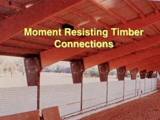
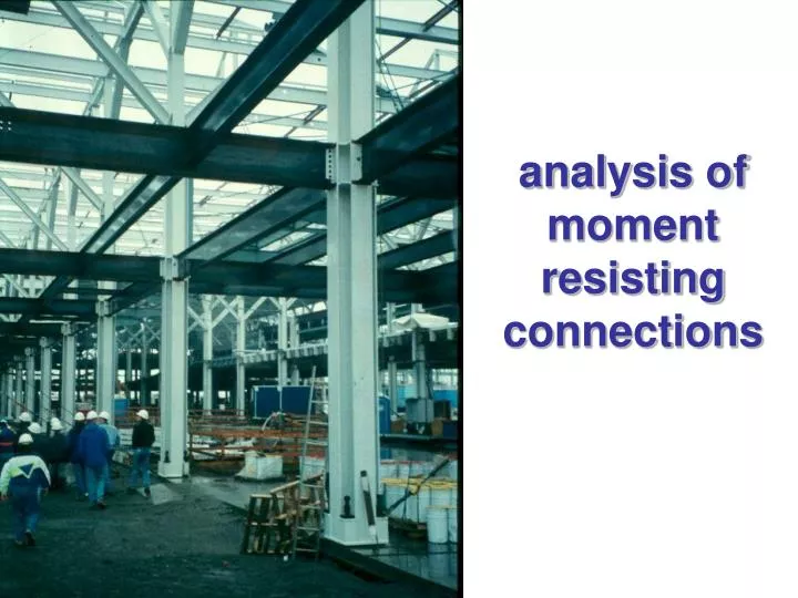
analysis of moment resisting connections. basic principles of connection design. Provide as direct a load path as possible Avoid complex stress conditions Weld in the shop, bolt on site. Welded connections. M. moment connection of an I-Beam. Bending moment is carried mainly by the flanges

E N D
basic principles of connection design • Provide as direct a load path as possible • Avoid complex stress conditions • Weld in the shop, bolt on site
M moment connection of an I-Beam • Bending moment is carried mainly by the flanges • Therefore connect flanges for moment transfer
C = T M d Resultant tension force T = M/d moment connection of an I-Beam • Welded connection • Fillet welds • Full penetration welds • Compression transfer can also be accomplished through direct bearing
V shear connection of an I-Beam • Shear is carried mainly by the web • Therefore connect the web for shear transfer
V shear connection of an I-Beam • Fillet welds in shear are commonly used • Connect entire web and adjust weld size to suit shear load
M moment connection of a plate Stress in weld σ = M (d/2) / I = M (d/2) / (ad3/12) [kN/m2] q = σ a = M (d/2) / (d3/12) = M (d/2) / I’ [kN/m] Where I’ = I/a Then choose a weld size a that will carry q d q = σ.a where a = weld size
M moment connection of a plate Can also use simplified approach: • Break moment into a force couple • Choose a suitable weld size • Then calculate the required length of the weld to carry the tension force T C = T d Resultant tension force T = M/d q = T/l where l = weld length
V V M = V.e Centroid of weld group e welded shear plate
simplified approach V.e’/d • Break eccentric load up into a vertical force along the vertical weld and a pair (couple) of horizontal forces along the horizontal welds • Then choose lengths of welds to carry the calculated forces V d V V.e’/d e’
V V M = V.e M = V.e “Stress” calculations +
V “Stress” calculations for vertical force V qV Divide shear equally amongst all the weld lines q = V / (total length of weld) Choose a weld size that can carry the “stress” q Note q is actually a force per length [kN/m]
M = V.e “Stress” calculations for Moment M = V.e Treat the weld group as a cross-section subjected to a torsional moment I’p2 = I’x2 + I’y2 where I’ = I/a qAx = M yA / I’p qAy = M xA / I’p qAM = (qAx2 + qAy2)0.5 Similarly for point B Then select weld size for max. q xB xA qAx A qAy qAM yA qBy yB qBM B qBx
“Stress” calculations for combined V and M qAx A Combine the weld “stress” components from the vertical force and the torsional moment qA = [qAx2 + (qAV + qAy)2]0.5 Similarly for point B or any other point that might be critical Then select weld size for the maximum value of q qAy qAV V qA M = V.e B
example of a complex connection Column tree for Times Square 4, NYC
C = T M d Resultant tension force T = M/d moment splice of an I-Beam • Bolted connection • Divide tension and compression resultant equally between bolts
shear connection in bridge diaphragm girder(Alex Fraser Bridge)
V shear connection of an I-Beam • Bolted connections to transfer shear are commonly used • Connect entire web to avoid stress concentrations and shear lag
shear connection via end plate End plate Coped flanges to fit in between column flanges
moment connection with fully welded end plate Tmax Ti = Tmax (hi / hmax) M = Σ Ti hi Ti M hmax hi C = Σ Ti
Ti + TM M pre-tensioned Moment Connection Apply both tension and compression forces to pre-tensioned bolts. Compression force can be seen as a release of the tension force. M =
P e P Centroid of bolt group M = Pe bolted shear plate
vertical load Divide the force by n, the number of bolts VP = P / n VP P VP
moment Treat the bolt group as a cross-section subjected to a torsional moment Ip = Σi A ri2 = Σi A (xi2 + yi2) and with I’P = IP/A FxM = M yi / I’p FyM = M xi / I’p FMi = (FxM2 + FyM2)0.5 Then select a bolt size for the maximum force FM xi bolt i FxM ri FMi FyM yi M bolt area A
P M = Pe combined vertical force and moment FxM FyM Fmax VP Fmax = [FxM2 + (FyM + VP)2]0.5 Then select a bolt size for the maximum force Fmax