Download
1 / 36
360 likes | 495 Views
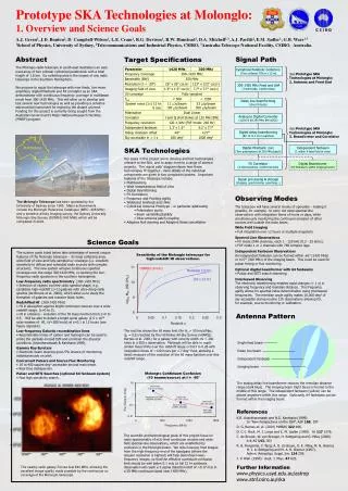
Darwin. AUSTRALIA. Brisbane. Sydney. Perth. +. Molonglo. Adelaide. Canberra. Melbourne. Hobart. Molonglo SKA Prototyping and MNRF. Molonglo SKA Prototyping and MNRF. Research Team:

E N D
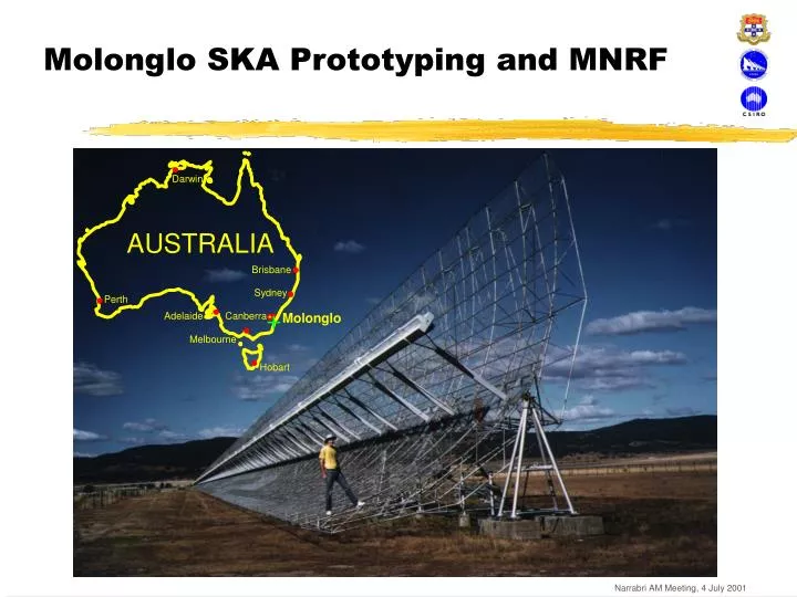
Darwin AUSTRALIA Brisbane Sydney Perth + Molonglo Adelaide Canberra Melbourne Hobart Molonglo SKA Prototyping and MNRF Narrabri AM Meeting, 4 July 2001
Molonglo SKA Prototyping and MNRF Research Team: Anne Green1, John Bunton2, Duncan Campbell-Wilson1, Lawrence Cram1, Ralph Davison1, Dick Hunstead1, Daniel “Mitch” Mitchell1,3, Andrew Parfitt2, Elaine Sadler1, George “Ñima” Warr1,3 [1] School of Physics, University of Sydney [2] Telecommunications and Industrial Physics, CSIRO [3] Australia Telescope National Facility, CSIRO Narrabri AM Meeting, 4 July 2001
What is the SKA? The next generation radio telescope The Square Kilometre Array radio telescope: • Large collecting area for high sensitivity (1 km2) • Array elements (stations) distributed over a wide area for high resolution (~4000 km) • For good uv plane coverage, stations can’t be too sparse Narrabri AM Meeting, 4 July 2001
Radio telescope sensitivityincreasing logarithmically with time Narrabri AM Meeting, 4 July 2001
SKA will provide higher sensitivity and resolution HST VLA SKA Narrabri AM Meeting, 4 July 2001
Radio frequency interference (RFI)must be excised to get high sensitivity Narrabri AM Meeting, 4 July 2001
For high resolution array stations are distributed across a continent Narrabri AM Meeting, 4 July 2001
Phased array (Netherlands) 1000km Narrabri AM Meeting, 4 July 2001 (Courtesy NFRA)
Luneberg Lens (ATNF) Narrabri AM Meeting, 4 July 2001
Luneberg Lens Focusing Action (ATNF) Narrabri AM Meeting, 4 July 2001
Parabolic Reflector Array (SETI Institute, USA) Narrabri AM Meeting, 4 July 2001
Aerostatically mounted receiver aboveLarge Adaptive Reflector (Canada) Narrabri AM Meeting, 4 July 2001
Large [Arecibo-like] Reflectors (China) Narrabri AM Meeting, 4 July 2001
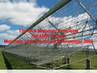
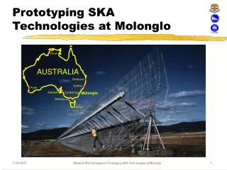
Darwin AUSTRALIA Brisbane Sydney Perth + Molonglo Adelaide Canberra Melbourne Hobart Cylindrical Parabolic CollectorMolonglo (USyd, ATNF, CSIRO) Narrabri AM Meeting, 4 July 2001
Molonglo SKA Prototyping and MNRF. Overview • Molonglo telescope is an E-W array of two collinear cylindrical paraboloids. • total length of1.6 km (2 x 800m with 15 m gap between them). • Collecting area 18,000 m2(largest in the Southern Hemisphere). • We propose to equip the telescope with new feeds, low-noise amplifiers, digital filterbanks and FX correlator as an SKA prototype with continuous frequency coverage in multibeam mode from 300-1420 MHz. • Allows development and testing of several new technologies. • Provides a sensitive instrument for exploring the distant universe. • Funding for this project is currently being sought from the Australian Government's Major National Research Facilities (MNRF) program. • The Molonglo Telescopehas been operated by the University of Sydney since 1965. Major achievements include the Molonglo Reference Catalogue (MRC; 408 MHz) and a sensitive all-sky imaging survey, Sydney University Molonglo Sky Survey (SUMSS; 843 MHz) thatwill be completed in 2003. Narrabri AM Meeting, 4 July 2001
Target Specifications Narrabri AM Meeting, 4 July 2001
Molonglo SKA Prototyping and MNRF Main science goals: Low-frequency radio spectrometry (300-1420 MHz) • Selection of objects via their radio spectral shape, e.g. candidate high-redshift (z>3) galaxies with ultra-steep radio spectra (de Breuck et al. 2000), which allow us to study the formation of galaxies and massive black holes. Redshifted HI (300-1420 MHz) • HI in absorption against bright continuum sources over a wide redshift range (z=0 to 3). • HI in emission - evolution of the HI mass function from z=0 to 0.5. Will be able to detect a bright spiral galaxy(2.5 x 10¹⁰ solar masses of HI, DV=200 km/s) at z=0.1 in 12 hours. Narrabri AM Meeting, 4 July 2001
Selection of high-z radio galaxies by radio spectral index • de Breuck (PhD 2000) - ultra-steep radio spectra (a < -1.3) can select (some) high-z galaxies • K magnitude is a good initial redshift estimator • BUT two-point spectral index is crude (finds only ~1 candidate per 15-20 deg2) - we will be >5 times more sensitive and can use detailed radio spectra. Narrabri AM Meeting, 4 July 2001
Molonglo ableto measure evolution of HI mass function over z=0.03 to 0.26 HIPASS (8 min) Molonglo (12 hr) H0 = 50 km/s/Mpc, q0 = 0.5 (10 x 12 hr) 1.7 deg2 field log10 Mlim (HI) (M⊙) Galaxy with velocity width DV = 200 km/s Narrabri AM Meeting, 4 July 2001
Science Goals ctd… Low-frequency Galactic recombination lines • Recombination lines of carbon and hydrogen can be used to probe the partially-ionized ISM and constrain the physical conditions (Anantharamaiah & Kantharia 1999). Gamma Ray Bursters • Electronic beam steering gives 5% chance of monitoringinstantaneously on alert. Concurrent Pulsars and Source Flux Monitoring • 18 to 400 deg2 accessible around main beam. • Real time dedispersion. Pulsar and SETI Searches (optional 64 fanbeam system) • Fast high sensitivity search. Narrabri AM Meeting, 4 July 2001
Molonglocontinuous uv coverage produces excellent image quality Narrabri AM Meeting, 4 July 2001
beam size: 112” x 112” csc|d| Rengelink et al 1997 WENSS 325 MHz beam size: 43” x 43” csc|d| beam size: 26” x 26” csc|d| Bock et al 1999 SUMSS 843 MHz Wall 1994 1420 MHz Molonglo Continuum Confusion (10 beams/source) at δ= -60° Narrabri AM Meeting, 4 July 2001
SKA Technologies • Multibeaming • Wide instantaneous field of view • Digital Beamforming • FX Correlators • Frequency and Pointing Agility • Wideband linefeeds and LNAs • Cylindrical Antenna Prototype – in particular addressing • Polarisation purity • Beam variability/stability • Inter-antenna patch coupling • Adaptive Null steering and Adaptive Noise cancellation Narrabri AM Meeting, 4 July 2001
Observing Modes Wide Field Imaging • Full integration over 12 hours or multiple snapshots. Spectral Line Observations • FX mode 2048 channels, each 1 - 120 kHz (0.2 - 25 km/s). • FXF mode 1 or 2 channels with 768 complex lags. Independent Fanbeam Observations • An independent fanbeam can be formed within ±6° (1420 MHz) or ±27° (300 MHz) of the imaging beam, e.g., for pulsar timing or flux monitoring. Interleaved Observing [Rapid electronic changes (< 1 s) in frequency & meridian distance] • Frequency agility spectral index determination. • Meridian angle agility 10,000 deg2 of sky accessible during routine 12h observations, e.g., source monitoring or calibration. Optional digital beamformer with 64 fanbeams • Pulsar and SETI search observing. Narrabri AM Meeting, 4 July 2001
Cylindrical Parabolic Collectors (Two collinear 778 m x 12 m) 300-1420 MHz Feed and LNA (7,400 feeds, 14,800 LNAs) Single feed beam Delay line beam Independent fanbeam Imaging beam Delay line beamforming (Over 9 feeds) Analog to Digital Converter (1,600 8 bit 250 MHz BW ADCs) Digital delay beamforming (80 10 m x 10 m patches) Digital filterbank (160) (Two polarisations @ 250 MHz/patch) Independent fanbeam (1 within 9 feed field of view) FX Correlator (3,160 baselines, 2,048 channels) Digital Beamformer (64 fanbeams within imaging beam) [Requires extra funding] Signal processing & storage (imaging, spectrometer, searching...) Signal Path and Antenna Pattern Narrabri AM Meeting, 4 July 2001
Collector Geometry The telescope’s collector consists of two cylindricalparaboloids, 778m x 12m, separated by 15m and aligned east-west (total area 18,000 m2). The telescope is steered by mechanical rotation of the cylindrical paraboloids about theirlong axis, and by electronic delays of the feed elements along the arms. The resulting ‘alt-alt’ system can follow fields south of declination -30° for ±6 hours. The original parabola shape was designed to be accurate for operation at 1.4 GHz. The reflecting mesh was designed for operation at 408 MHz and will need to be replaced for operation above ~1 GHz. MD=Meridian Distance Narrabri AM Meeting, 4 July 2001
xfocus Molonglo parabola design accurate to > 1400 MHz Piecewise linear fit to parabola shape Flat mesh tied on supports at points shown • Mesh supported at 0.6 m (2 ft) intervals in x direction. • Each section gives the same error for a linear fit to a parabola. • Gives only 0.1 dB loss at 1420 MHz. Narrabri AM Meeting, 4 July 2001
Original 408 MHz mesh needs replacing for operation above ~1 GHz 843 MHz NS 1420 MHz NS ~75K ground leakage Original mesh designed for 408 MHz (12mm NS x 25mm EW) Narrabri AM Meeting, 4 July 2001
Resurfacing Issues • Wind loading • Pointing accuracy Not a major issue if using a mesh rather than a solid surface. • No noticeable extra loading at Parkes after resurfacing (with porous surface). • Pointing accuracy degraded at ATCA in windy conditions and low elevations after replacing with solid surface. Possibly due to increased vacuum on lee side of dish. Narrabri AM Meeting, 4 July 2001
Patch positions on reflectors -800 0 800 Distance (m) Synthesised Beam Shape Beam Shape The synthesised beam shape for a possible configuration of antenna patches on the telescope is shown. This configuration has a contiguous patch covering a third of the telescope area for forming 1.3’ beams for pulsar or SETI searches. The remaining part of the telescope is more sparsely covered (with positions calculated from a simple grading function) to give good imaging resolution. Narrabri AM Meeting, 4 July 2001
Wide Band Feeds Required Single feed covering 300-1420 MHz desirable • Vivaldi antenna array suitable? • ASTRON THEA operates over 750-1500 MHz • Highest performance at high frequencies. At lower frequencies: • Higher sky temperature • Increased source counts per steradian • Larger beam size Narrabri AM Meeting, 4 July 2001
45 Gain 30 15 |S| (dB) 0 Output Match S22 Input Match S11 -15 -30 300 1400 850 Frequency (MHz) Wide band ambient temperature low noise amplifiers required Prototype design for 400-1200 MHz HEMT based LNA (Ralph Davison) • ~20K noise temperature • Ambient temperature operation • Likely to be able to extend to operate over 300-1400 MHz • Design simplifications possible if higher input impedance from antenna (designed for 50W input impedance) • Good starting point for migration to MMIC design Narrabri AM Meeting, 4 July 2001
Beamformer and Correlator Beamforming and Digital Filterbanks for one of 44 bays Analog delay line beamforming Accuracy /4 Each polarisation RF 0.3 to 1.4GHz LO 2.2 to 0.9GHz IF at 2.5 GHz Quadrature baseband detection Dual 250 MSamples/s 8-bit A/Ds generating a complex 250 MHz signal Digital Beamforming Fine delays accuracy /16 Delay corrects for average analog delay error Arbitrary and time varying grading Modifiable beam shape with meridian distance Resources for adaptive null steering 250 MHz complex digital filterbanks 120 kHz frequency channels Single FPGA implementation Adaptive noise cancellation on a per channel basis Narrabri AM Meeting, 4 July 2001
RFI at Molonglo 200-1500 MHz (Measured 25 June 2001) UHF TV VHF TV GSM Narrabri AM Meeting, 4 July 2001
Molonglo SKAPrototype(Operating by 2004-2005) • New line feeds: prototypes for SKA cylindrical doublet antennas • New low-noise amplifiers • Resurface telescope to operate at higher frequency • Photonics for LO distribution, signal gathering and beam forming • Wide-band FX correlator • ‘Software telescope’ - computerised control, beam forming and data acquisition • Automated remote operation, data pipeline • Result: 300-1400 MHz radio ‘spectrometer’ with >5 times increase in continuum sensitivity, high dynamic range, fully-sampled uv plane. New spectral-line capability for redshifted HI. Narrabri AM Meeting, 4 July 2001
Summary • Science: Studies of the high-redshift universe (high-z galaxies, evolution of HI mass function) • Technology: prototype for SKA cylindrical antennas, software beamforming, high dynamic range observing with fully-sampled uv plane • Community use: New national facility that re-opens the radio spectrum below 1.4 GHz, operating by 2005 as a fully-automated remote observing telescope with a data reduction pipeline Narrabri AM Meeting, 4 July 2001