Download
1 / 1
10 likes | 167 Views
Prototype SKA Technologies at Molonglo: 1. Overview and Science Goals A.J. Green 1 , J.D. Bunton 2 , D. Campbell-Wilson 1 , L.E. Cram 1 , R.G. Davison 1 , R.W. Hunstead 1 , D.A. Mitchell 1,3 , A.J. Parfitt 2 , E.M. Sadler 1 , G.B. Warr 1,3

E N D
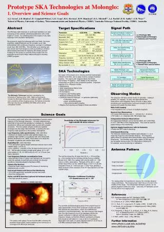
Prototype SKA Technologies at Molonglo: • 1. Overview and Science Goals • A.J. Green1, J.D. Bunton2, D. Campbell-Wilson1, L.E. Cram1, R.G. Davison1, R.W. Hunstead1, D.A. Mitchell1,3, A.J. Parfitt2,E.M. Sadler1, G.B. Warr1,3 • 1School of Physics, University of Sydney, 2Telecommunications and Industrial Physics, CSIRO, 3Australia Telescope National Facility, CSIRO. Australia. Signal Path Cylindrical Parabolic Collectors (Two collinear 778 m x 12 m) SeePrototype SKA Technologies at Molonglo: 2. Antenna and Front End 300-1420 MHz Feed and LNA (7,400 feeds, 14,800 LNAs) Delay line beamforming (Over 9 feeds) Analog to Digital Converter (1,600 8 bit 250 MHz BW ADCs) SeePrototype SKA Technologies at Molonglo: 3. Beamformer and Correlator Digital delay beamforming (80 10 m x 10 m patches) Digital filterbank (160) (Two polarisations @ 250 MHz/patch) Independent fanbeam (1 within 9 feed field of view) FX Correlator (3,160 baselines, 2,048 channels) Digital Beamformer (64 fanbeams within imaging beam) Signal processing & storage (imaging, spectrometer, searching...) Darwin AUSTRALIA Brisbane Sydney Perth + Molonglo Adelaide Canberra Melbourne Hobart Abstract The Molonglo radio telescope in south-east Australia is an east-west array of two colinear cylindrical paraboloids with a total length of1.6 km. Its collecting area is the largest of any radio telescope in the Southern Hemisphere. We propose to equip the telescope with new feeds, low-noise amplifiers, digital filterbank and FX correlator as an SKA demonstrator with continuous frequency coverage in multibeam mode from 300-1420 MHz. This will allow us to develop and test several new technologies as well as providing a sensitive astronomical instrument for exploring the distant universe. Funding for this project is currently being sought from the Australian Government's Major National Research Facilities (MNRF) program. Target Specifications • SKA Technologies • Our goals in this project are to develop and test technologies relevant to the SKA, and to apply them to a range of science projects. The ‘signal path’ diagram shows how these technologies fit together - more details of the individual components are given in two companion posters. Important features of the telescope include: • Multibeaming • Wide instantaneous field of view • Digital Beamforming • FX Correlators • Frequency and Pointing Agility • Wideband linefeeds and LNAs • Cylindrical Antenna Prototype – in particular addressing • Polarisation purity • Beam variability/stability • Inter-antenna patch coupling • Adaptive Null steering and Adaptive Noise cancellation Photo D. Bock • Observing Modes • The telescope will have several modes of operation - making it possible, for example, to carry out deep spectral-line observations with integration times of hours or days, while simultaneously monitoring the continuum emission of other sources well outside the main beam. • Wide Field Imaging • Full integration over 12 hours or multiple snapshots. • Spectral Line Observations • FX mode 2048 channels, each 1 - 120 kHz (0.2 - 25 km/s). • FXF mode 1 or 2 channels with 768 complex lags. • Independent Fanbeam Observations • An independent fanbeam can be formed within ±6° (1420 MHz) or ±27° (300 MHz) of the imaging beam. This could be used for pulsar timing or flux monitoring. • Optional digital beamformer with 64 fanbeams • Pulsar and SETI search observing. • Interleaved Observing • The electronic beamforming enables rapid changes (< 1 s) in observing frequency and meridian distance. The frequency agility allows for spectral index determination using interleaved frequencies. The meridian angle agility makes 10,000 deg2 of sky accessible during routine 12h observations allowing for, for example, source monitoring or calibration. The Molonglo Telescope has been operated by the University of Sydney since 1965. Major achievements include the Molonglo Reference Catalogue (MRC; 408 MHz) and a sensitive all-sky imaging survey, the Sydney University Molonglo Sky Survey (SUMSS; 843 MHz) which will be completed in 2003. Science Goals • The science goals listed below take advantage of several unique features of the Molonglo telescope - its large collecting area, wide field of view and fully-sampled uv coverage (i.e. excellent sensitivity to diffuse and extended radio sources with complex structure). The new system will give continuous spectral coverage over the range 300-1420 MHz, re-opening the low-frequency radio spectrum in the southern hemisphere. • Low-frequency radio spectrometry (300-1420 MHz) • Selection of objects via their radio spectral shape, e.g. candidate high-redshift (z>3) galaxies with ultra-steep radio spectra (de Breuck et al. 2000), which allow us to study the formation of galaxies and massive black holes. • Redshifted HI (300-1420 MHz) • HI in absorption against bright continuum sources over a wide redshift range (z=0 to 3). • HI in emission - evolution of the HI mass function from z=0 to 0.5. Will be able to detect a bright spiral galaxy(2.5 x 10¹⁰ solar masses of HI, DV=200 km/s) at z=0.1 in 12 hours (see figure opposite). • Low-frequency Galactic recombination lines • Recombination lines of carbon and hydrogen can be used to probe the partially-ionized ISM and constrain the physical conditions (Anantharamaiah & Kantharia 1999). • Gamma Ray Bursters • Electronic beam steering gives 5% chance of monitoringinstantaneously on alert. • Concurrent Pulsars and Source Flux Monitoring • 18 to 400 square deg2 accessible around main beam. • Real time dedispersion. • Pulsar and SETI Searches (optional 64 fanbeam system) • Fast high sensitivity search. Sensitivity of the Molonglo telescope for high-redshift HI observations. HIPASS (8 min) Molonglo (12 hr) (10 x 12 hr) log10 Mlim (HI) (M) Antenna Pattern The red line shows the HI mass limit (for H0 = 50 km/s/Mpc, q0 = 0.5) reached by the HI ParkesAll-Sky Survey (HIPASS; Barnes et al. 2001) for a galaxy with velocity width DV = 200 km/s in a 500 sobservation. Molonglo will be ableto reach similar mass limits over the redshift range z=0.03 to 0.26 with integration times of ~120 hours per 1.7 deg2 field, allowing a directmeasure of the evolution of the HI mass function over this redshift range. Single feed beam Delay line beam Independent fanbeam Imaging beam Molonglo Continuum Confusion (10 beams/source) at d= -60° The analog delay line beamformer reduces the meridian distance range (dark blue). The imaging beam (light blue) is formed in the middle of this range. The independent fanbeam (yellow) can be placed anywhere within this range. Optionally, 64 fanbeams can be formed within the imaging beam. References K.R. Anantharamaiah and N.G. Kantharia (1999). In “New Perspectives on the ISM”, ASP 168, 197 D. G. Barnes et. al. (2001) MNRAS 322 486. D. C.-J. Bock, M. I. Large and E. M. Sadler (1999). AJ 117 1578. C. de Breuck, W. van Breugel, H. Rottgering and G. Miley (2000). A & AS 143, 303 R. B. Rengelink, Y. Tang, A. G. de Bruyn, G. K. Miley, M. N. Bremer, H. J. A. Röttgering and M. A. R. Bremer (1997). Astron. Astrophys. Suppl. Ser. 124 259. J. V. Wall (1994). Aust. J. Phys. 47 625. Further Information www.physics.usyd.edu.au/astrop www.atnf.csiro.au/ska beam size: 112” x 112” csc|d| Rengelink et al 1997 WENSS 325 MHz beam size: 43” x 43” csc|d| beam size: 26” x 26” csc|d| Bock et al 1999 SUMSS 843 MHz Wall 1994 1420 MHz The scientific and technological goals of this project focus on radio spectrometry of mJy-level continuum sources and wide-field spectral-line observations, which are unaffected by confusion inthe Molonglo beam. We note however, that images from the high-frequencyend of the bandpass (where the angular resolution is highest) will help deconfuse lower-frequency images, so that the effective continuumconfusion limit should be well below 0.1 mJy (a full 12 hr synthesisobservation will reach a 5 sigma detection limit of ~0.17 mJy in a 30 MHzcontinuum band near 1400 MHz). The nearby radio galaxy Fornax A at 843 MHz, showing the excellent image quality made possible by the continuous uv coverage of the Molonglo telescope.