Download
1 / 23
230 likes | 236 Views
Status of Bunch-by-bunch Feedback and Diagnostic Systems. Weixing Cheng on behalf of BI group Jul-24-2018, NSLS-II High Intensity Review. Outline. BxB Feedback Status and Observations BxB Feedback Overview and Performance Fast ion, RW instability measurement

E N D
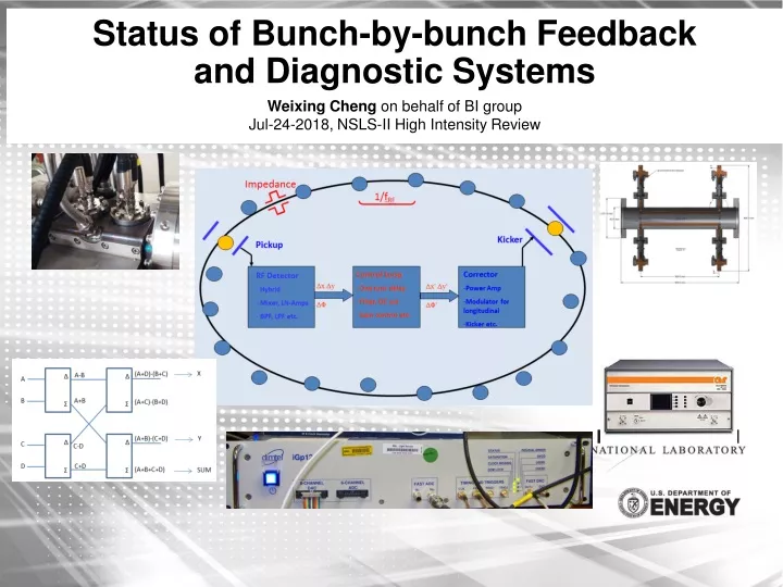
Status of Bunch-by-bunch Feedback and Diagnostic Systems Weixing Cheng on behalf of BI group Jul-24-2018, NSLS-II High Intensity Review
Outline • BxB Feedback Status and Observations • BxB Feedback Overview and Performance • Fast ion, RW instability measurement • Single bunch instabilities suppression • Measurements using BxB feedback • Other Diagnostic System Performance • Pinhole camera measurements • Bunch length measurements • FPM, improvement for hybrid fill • BPM intensity and fill pattern dependency • Future developments • Summary
BxB feedback system - Overview • Transverse BxB feedback designed to have <200ms (75 turns) damping time. Fastest instability was estimated to be ion-related. • In house developed pickup, hybrid box, stripline kickers (30cm, >10kOhm Rsh up to 200MHz) • Commercial digitizer (12-bit 500MHz ADC, 14-bit DAC) • High power amplifiers (10kHz – 250MHz, 500W) • 1/2’’ Heliax cables for kickers and 3/8’’ heliax for monitor signals • The system was commissioned in May 2014 and have been operated reliable since then, with extra diagnostic capabilities. • Suppress coupled bunch instabilities (damping time < 1ms) • <8pm.rad vertical emittance achievable at 375mA • Suppress single bunch TMCI (resistive feedback). Ib > 6mA • Dominant instabilities: fast ion + resistive wall • Hint of narrow band impedance measured with growth rate of individual modes • Parasitic single bunch tune measurement • Bunch cleaning • Transient excitation for lattice measurement • Transfer function measurement etc. 38mA/1000 bunches
BPM Pickups and Stripline Kickers (BxB FB) • Dedicated button type BPM pickups at large beta locations. • Same geometry as normal LA-BPM (7mm diameter). • Detection at 1.5GHz (reserved BPMs without ante-chamber) • 3/8’’ Heliax cables • 30-cm long stripline, two plates • KEKB type feedthrough (Kyocera) • Same design for H/V kickers • Zc matched to 50 Ohm • Rsh > 10kOhm (up to 200MHz) 30 cm plate Ceramic V-cut Ceramic Max. 35ºC @ 375mA, at ceramic, Vrf = 3MV
BxB feedback digitizers (iGp12) • 12-bit high speed ADC • FPGA, programmable FIR filters, dly/gain control • 14-bit high speed DAC, differential outputs • Precise timing adjustment • Integrated IOC, EPICS • Bunch cleaning • Bunch by bunch diagnostic capability SB Tune 4-tap FIR
BxB feedback system measurements - 1(Fast ion and RW at operation current) • RW growth rate ~ 1 ms-1, with all ID gaps closed. 375mA, Cx/Cy = 2/2 • Ion hump around mode # -80 to -40, fast grow rate but tends to saturate. Ion instability varies with current, fill pattern, Y emittance, chromaticity, vacuum condition etc. • Damping rate ~ 4.7 ms-1(damping time 213ms, ~81 turns), with nominal feedback gain settings. Ion hump RW Jun 2018, 375mA, 3DW, Cx/Cy = 2/2, ey = 31pm.rad, Pavg = 5.1nTorr, FBY 3ms OFF Ion hump RW NIM A 861 (2017) 38-45 Aug 2016, 250mA, 3DW, Cx/Cy = 2/2, ey = 58pm.rad, Pavg = 3.8nTorr, FBY 10ms OFF RW Ion
BxB feedback system measurements - 1(Fast ion and RW at operation current – cont.) Beam size along the bunch train Ion burst during normal operations Red – Pavg = 5.8nT; P19 = 10.7nTorr; Sy_BMA = 41.5mm, 375mA Blue – Pavg = 5.5nT; P19 = 4.2nTorr; Sy_BMA = 19.9mm, 375mA Mode -35 Mode -36 p*Frf + m*Frev + fy • Vertical TbT position spikes greater than 40 mm. • Vertical size burst was observed at pinhole cameras at the same time (~10Hz rate) • BxB feedback saw correction signals near 10MHz (ion frequency hump). • Fast profile monitor will provide extra information of the instabilities. • Identify the ion burst location using global TbT data
BxB feedback system measurements - 2(Coupled bunch mode growth rate measurement) Growth rate fitting of individual coupled bunch mode Ion hump Measured growth rate of coupled bunch instability modes in vertical plane Peaks (arrow locations) are likely from the newly installed IDs. Systematic studies can be done with the technique.
z z y y BxB feedback system measurements - 3(Single bunch TMCI instability) IPAC2016 TUPOR033 FB OFF FB ON fy and fy – fs meet at Ib ~ 0.8mA => TMCI Y size blows up at threshold current, tilted profile observed The TMCI instability was suppressed with pure resistive feedback > 6mA single bunch can be stored with feedback ADC saturates at high single bunch current, with optimized RF attenuator settings.
BxB feedback system measurements - 4(Tune measurement from single bunch) IPAC2018 WEPAF011 PRAB 19, 104401 (2016) ID04 25mm 6.1mm • Tune related measurements • Single bunch current dependency • Total beam current dependency • Amplitude dependency • ID gap effect • Tune drifts along the bunch train • Chromaticity measurement • Tune feedback (dynamic correction) etc. * 3 damping wigglers, 10 IVUs and 4 EPUs gap closed
BxB feedback system measurements - 5(Resonant excitation for lattice measurement) IPAC2017 MOPAB151 PRAB 20, 112802 (2017) On-demand excitation of diagnostic bunches, ~1% of total charge. Negligible disturbance to the beam. Gated processing to have global BPM TbT data of diagnostic bunches => lattice characterization Techniques can be used for other machine physics developments FB ON FB OFF Gated Excitation
BxB feedback system measurements - 6(Feedback gain optimization) Excess feedback gain can excite the inter-bunch mode (emittance increase) => balance the coupled bunch instability suppression and high single bunch modes. Analog front end detection sensitivity and noise level. (Ultra low noise desired) Digital feedback loop optimization Chromaticity and per bunch current The effect is mainly in vertical plane due to a flat beam. Horizontal plane is equally important for ultra-low emittance SR. Beam lifetime is affected as well due to emittance changes. Ib: 0.3 - 0.4mA 230mA/1000 bunch Unstable l = ±1, ± 2,… +5/+5 Residual dipole l = 0 0.44mA, 1-bunch +2/+2
BxB feedback system measurements - 7(Longitudinal coupled bunch instability) • Longitudinal CBI was observed at high current operation in 2016. It’s not seen now at 375mA user operation with 3DWs, however, it is still observed with bare lattice. The instability has been confirmed with different measurements: • Button spectrum • Bunch by bunch feedback mode analysis • Streak camera dual sweep image • Bunch centroid motion from FPM scope • Longitudinal BxB feedback tested with stripline as kicker, a dedicated longitudinal kicker (and amplifiers) with higher shunt impedance is desired. The system will be helpful to measure longitudinal mode growth rate even with no CBI observed. Bare lattice, 350mA Unstable modes ~ 563 Head of bunch train +200ns +400ns (CBI) +1000ns (CBI) Feb-10-2016, 305mA/1000bunches
Status of other diagnostic systems (SR) • Current monitors • DCCT works fine at higher current (full range 1A). Max. temp. of sensor ~35 degC @375mA • FPM needs improvement for future hybrid fill patterns => high current single bunch • Development of fill pattern monitor using synchrotron radiations • Position monitors • BPM resolution: <1mm@TBT; ~200nm@FA; 200nm long-term stability (8-hrs, 0.1degC) • Small current and fill pattern dependency (< 5mm at low current; <1mm p-p above 100mA) • Attenuator dependency corrected • Button temp. ~ 29 degC (375mAm 3MV, BPM21-8 button assembly body) • Gated processing and fast glitch detection allow advanced beam measurements and instability registration • Possible to improve the position resolution with new signal processing algorithm • New electronics under development for better long term stability and more FPGA resources • 500MHz digitizer for bunch-by-bunch position measurement • Profile monitors (SLM, XDB-BMA, XDB-3PW) • Visible SLM (Spatial resolution ~60 mm, longitudinal resolution <2ps; air turbulence issue) • XDB-BMA and XDB-3PW work fine, with <1 turn fast profile measurement • Propose to further development the high dynamic range bunch purity monitoring system (Bunch cleaning is integrated with BxB feedback)
FPM measurements with hybrid fill pattern Digitizer close to saturate Single bunch Satellite bunches ~7ps phase transient Possible to measure fill pattern with TCSPC. Counting time has to be balanced between dynamic range and precision. To be integrated in to EPICS controls. X-ray photon diode can have 10-8 dynamic range Digitizers close to saturate with ~1mA per bunch Adding 10dB attenuator solved saturation issue, but makes the 1000-bunch measured current and centroid more noisy. Also, bunches with small current can be below the threshold voltage.
BPM Gated signal processing and applications MethodsX 5 (2018) 626-634 • Gated signal processing improves the TbT resolution, for single bunch (or short bunch train) fills. • Timing alignment of gates is critical. • Gated TbT data with diagnostic bunches has been used for “transparent” lattice characterization/correction, combined with transient excitation function of BxB feedback system. • Simultaneous orbit measurement from two gates can be useful for collective effect studies. Eliminating machine drifts/jitters. BPM gated position measurement has many other applications. • Two gates implemented, more gates possible with new FPGA. Bunch by bunch position measurement will be even more helpful (“1320 gates”) Y’ local bump at ID3
Fast glitch detection IPAC2018 WEPAF010 • Motivation • Beam size spikes vacuum activity • Fast beam position detection at spikes • Fast beam profile detection • Implement of fast glitch detection • Dedicated BPM(s) to generate triggers • Gate enables detection of partial bunches motion • Inhibit top off injection transient • Global event distribution and data acquisition • Observations with the glitch detection function • Ion instabilities due to vacuum bursts • Orbit glitches Some of the spikes were correlated to vacuum activities Ion frequency
Diagnostic beamlines (SLM, XDB) IPAC2018 WEPAF012 IPAC2016 TUPOR033 360mA, 984.65/7.43 pm.rad Bare lattice, Vrf = 2.25MV. Bunch lengthening curves measured with bare lattice, 1DW and 3DWs. Vrf = 1.78MV BMA – hx = 0; bx = 3.7m; by = 25m 3PW – hx = 0.17 m; bx = 3.75m; by = 18.82m
Future developments • BxB Feedback System • Continue optimizing of feedback for high current operations • Advanced machine physics measurements • Accommodate hybrid fill patterns • Monitoring of possible longitudinal CBI at high current • development of longitudinal feedback system (?) • See uptick of high power amplifier faults for the past year • Other Diagnostic Systems • Continue developing the advanced tools based on the existing BPMs • R&D of new generation of BPM electronics • FPM improvements to be compatible with future hybrid fill patterns • Improve diagnostic beamlines • SLM: improve spatial resolution; fix air turbulence • XDB: X-ray bunch purity monitoring
Summary • BxB Feedback System has been working reliable since commissioning • Suppress transverse CBI up to highest achieved current (425mA) • Suppress single bunch TMCI (Ib > 6mA @ nominal chromaticity) • Stripline highest temperature (out of vacuum) is ~35 degC • Powerful diagnostic capability • Continue improving the system for higher total/single current operations • Most of the other diagnostic systems are working well. There are several systems can be improved: • FPM to be upgraded to accommodate large current single bunch filled in the ion gap • New developments of BPMs • Diagnostic beamline improvements (air turbulence, fast profile measure) Many thanks to colleagues in the Beam Instrumentation group and other groups who help construct, commission, operate and improve the diagnostic systems; thanks to Dmitel for discussion of advanced measurements using feedback digitizer.
Transverse Bunch-by-bunch Feedback (preliminary design) Var. Att Stretch fRF p.s. (A+D)-(B+C) A-B Δ Δ Hor. feedback x 3 A A+B B Σ (A+C)-(B+D) Σ LNA To ADC (A+B)-(C+D) Δ Δ C D C-D C+D (A+B+C+D) Σ Σ Syn. Osc Detection Trigger fRF AMP Multiplexer FIR filter + DAC 500MHz 12-bit ADC 500MHz 12-bit Delay Gain - FPGA Linux PC, control interface SDRAM