Download
1 / 75
810 likes | 1.34k Views
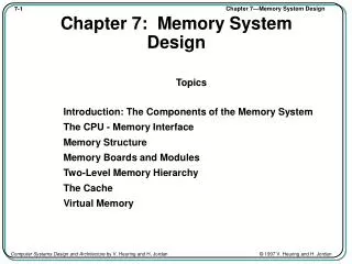
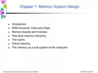
Chapter 7- Memory System Design. Introduction RAM structure: Cells and Chips Memory boards and modules Two-level memory hierarchy The cache Virtual memory The memory as a sub-system of the computer. Introduction. So far, we’ve treated memory as an array of words limited in size

E N D
Chapter 7- Memory System Design • Introduction • RAM structure: Cells and Chips • Memory boards and modules • Two-level memory hierarchy • The cache • Virtual memory • The memory as a sub-system of the computer
Introduction So far, we’ve treated memory as an array of words limited in size only by the number of address bits. Life is seldom so easy... • Real world issues arise: • cost • speed • size • power consumption • volatility • etc. • What other issues can you think of that will influence memory design?
In This Chapter we will cover– • Memory components: • RAM memory cells and cell arrays • Static RAM–more expensive, but less complex • Tree and Matrix decoders–needed for large RAM chips • Dynamic RAM–less expensive, but needs “refreshing” • Chip organization • Timing • Commercial RAM products" SDRAM and DDR RAM • ROM–Read only memory • Memory Boards • Arrays of chips give more addresses and/or wider words • 2-D and 3-D chip arrays • Memory Modules • Large systems can benefit by partitioning memory for • separate access by system components • fast access to multiple words • –more–
In This Chapter we will also cover– • The memory hierarchy: from fast and expensive to slow and cheap • Example: Registers->Cache–>Main Memory->Disk • At first, consider just two adjacent levels in the hierarchy • The Cache: High speed and expensive • Kinds: Direct mapped, associative, set associative • Virtual memory–makes the hierarchy transparent • Translate the address from CPU’s logical address to the physical address where the information is actually stored • Memory management - how to move information back and forth • Multiprogramming - what to do while we wait • The “TLB” helps in speeding the address translation process • Will discuss temporal and spatial locality as basis for success of cache and virtual memory techniques. • Overall consideration of the memory as a subsystem.
Fig. 7.1 The CPU–Main Memory Interface • Sequence of events: • Read: • 1. CPU loads MAR, issues Read, and REQUEST • 2. Main Memory transmits words to MDR • 3. Main Memory asserts COMPLETE. • Write: • 1. CPU loads MAR and MDR, asserts Write, and REQUEST • 2. Value in MDR is written into address in MAR. • 3. Main Memory asserts COMPLETE.
The CPU–Main Memory Interface - cont'd. • Additional points: • if b<w, Main Memory must make w/b b-bit transfers. • some CPUs allow reading and writing of word sizes <w. • Example: Intel 8088: m=20, w=16,s=b=8. • 8- and 16-bit values can be read and written • If memory is sufficiently fast, or if its response is predictable, • then COMPLETE may be omitted. • Some systems use separate R and W lines, and omit REQUEST.
Table 7.1 Some Memory Properties Symbol Definition Intel Intel IBM/Moto. 8088 8086 601w CPU Word Size 16bits 16bits 64 bitsm Bits in a logical memory address 20 bits 20 bits 32 bits s Bits in smallest addressable unit 8 8 8 b Data Bus size 8 16 64 2m Memory wd capacity, s-sized wds 220 220 232 2mxs Memory bit capacity 220x8 220x8 232x8
Big-Endian and Little-Endian Storage • When data types having a word size larger than the smallest • addressable unit are stored in memory the question arises, • “Is the least significant part of the word stored at the • lowest address (little Endian, little end first) or– • is the most significant part of the word stored at the • lowest address (big Endian, big end first)”? Example: The hexadecimal 16-bit number ABCDH, stored at address 0: msb ... lsb AB CD Little Endian Big Endian AB 1 1 CD CD 0 0 AB
Table 7.2 Memory Performance Parameters Symbol Definition Units Meaning ta Access time time Time to access a memory word tc Cycle time time Time from start of access to start of next access k Block size words Number of words per block b Bandwidth words/time Word transmission rate tl Latency time Time to access first word of a sequence of words tbl = Block time Time to access an entire block of words tl + k/b access time (Information is often stored and moved in blocks at the cache and disk level.)
C P U T a p e C a c h e M a i n M e m o r y D i s k M e m o r y M e m o r y Table 7.3 The Memory Hierarchy, Cost, and Performance • Compo- • nent • Access Random Random Random Direct Sequential • Capa- 64-1024+ 8KB-8MB 64MB-2GB 8GB 1TB • city, • bytes • Latency .4-10ns .4-20ns 10-50ns 10ms 10ms-10s • Block 1 word 16 words 16 words 4KB 4KB • size • Band- System System 10-4000 50MB/s 1MB/s • width clock Clock MB/s • Rate rate-80MB/s • Cost/MB High $10 $.25 $0.002 $0.01 Some Typical Values:† †As of 2003-4. They go out of date immediately.
Fig. 7.3 Memory Cells - a conceptual view Regardless of the technology, all RAM memory cells must provide these four functions: Select, DataIn, DataOut, and R/W. Select DataIn DataOut R/W This “static” RAM cell is unrealistic. We will discuss more practical designs later.
Fig. 7.4 An 8-bit register as a 1D RAM array The entire register is selected with one select line, and uses one R/W line Data bus is bi-directional, and buffered. (Why?)
Fig. 7.5 A 4x8 2D Memory Cell Array 2-4 line decoder selects one of the four 8-bit arrays 2-bit address R/W is common to all. Bi-directional 8-bit buffered data bus
Fig. 7.6 A 64Kx1 bit static RAM (SRAM) chip ~square array fits IC design paradigm Selecting rows separately from columns means only 256x2=512 circuit elements instead of 65536 circuit elements! CS, Chip Select, allows chips in arrays to be selected individually This chip requires 21 pins including power and ground, and so will fit in a 22 pin package.
Fig 7.7 A 16Kx4 SRAM Chip There is little difference between this chip and the previous one, except that there are 4, 64-1 Multiplexers instead of 1, 256-1 Multiplexer. This chip requires 24 pins including power and ground, and so will require a 24 pin pkg. Package size and pin count can dominate chip cost.
Fig 7.8 Matrix and Tree Decoders • 2-level decoders are limited in size because of gate fanin. • Most technologies limit fanin to ~8. • When decoders must be built with fanin >8, then additional levels of gates are required. • Tree and Matrix decoders are two ways to design decoders with large fanin: 4-to-16 line matrix decoder constructed from 2-input gates. 3-to-8 line tree decoder constructed from 2-input gates.
Fig 7.9 A 6 Transistor static RAM cell This is a more practical design than the 8-gate design shown earlier. A value is read by precharging the bit lines to a value 1/2 way between a 0 and a 1, while asserting the word line. This allows the latch to drive the bit lines to the value stored in the latch.
Figs 7.10 Static RAM Read Timing Access time from Address– the time required of the RAM array to decode the address and provide value to the data bus.
Figs 7.11 Static RAM Write Timing Write time–the time the data must be held valid in order to decode address and store value in memory cells.
Fig 7.12 A Dynamic RAM (DRAM) Cell Capacitor will discharge in 4-15ms. Refresh capacitor by reading (sensing) value on bit line, amplifyingacitor. Write: place value on bit line and assert word line. Read: precharge bit line, assert word line, sense value on bit line with sense/amp. This need to refresh the storage cells of dynamic RAM chips complicates DRAM system design.
Fig 7.13 DRAM Chip organization • Addresses are time-multiplexed on address bus using RAS and CAS as strobes of rows and columns. • CAS is normally used as the CS function. • Notice pin counts: • Without address multiplexing: 27 pins including power and ground. • With address multiplexing: 17 pins including power and ground.
Figs 7.14, 7.15 DRAM Read and Write cycles Typical DRAM Read operation Typical DRAM Write operation Data hold from RAS. Access time Cycle time Notice that it is the bit line precharge operation that causes the difference between access time and cycle time.
DRAM Refresh and row access • Refresh is usually accomplished by a “RAS-only” cycle. The row address is placed on the address lines and RAS asserted. This refreshed the entire row. CAS is not asserted. The absence of a CAS phase signals the chip that a row refresh is requested, and thus no data is placed on the external data lines. • Many chips use “CAS before RAS” to signal a refresh. The chip has an internal counter, and whenever CAS is asserted before RAS, it is a signal to refresh the row pointed to by the counter, and to increment the counter. • Most DRAM vendors also supply one-chip DRAM controllers that encapsulatethe refresh and other functions. • Page mode, nibble mode, and static column mode allow rapid access tothe entire row that has been read into the column latches. • Video RAMS, VRAMS, clock an entire row into a shift register where it canbe rapidly read out, bit by bit, for display.
Fig 7.16 A CMOS ROM Chip 2-D CMOS ROM Chip 00 1 0 1 0
Tbl 7.4 Kinds of ROM ROM Type Cost Programmability Time to program Time to erase Mask pro- Very At the factory Weeks (turn around) N/A grammed inexpensive PROM Inexpensive Once, by end Seconds N/A user EPROM Moderate Many times Seconds 20 minutes Flash Expensive Many times 100 us. 1s, large EPROM block EEPROM Very Many times 100 us. 10 ms, expensive byte
Memory boards and modules • There is a need for memories that are larger and wider than a single chip • Chips can be organized into “boards.” • Boards may not be actual, physical boards, but may consist of structured chip arrays present on the motherboard. • A board or collection of boards make up a memory module. • Memory modules: • Satisfy the processor–main memory interface requirements • May have DRAM refresh capability • May expand the total main memory capacity • May be interleaved to provide faster access to blocks of words.
C h i p S e l e c t s A d d r e s s A d d r e s s D e c o d e r m C S R / W R / W M e m o r y m C e l l A d d r e s s A r r a y D a t a s I / O s s s M u l t i p l e x e r s D a t a Fig 7.17 General structure of memory chip This is a slightly different view of the memory chip than previous. Multiple chip selects ease the assembly of chips into chip arrays. Usually provided by an external AND gate. Bi-directional data bus.
Fig 7.18 Word Assembly from Narrow Chips All chips have common CS, R/W, and Address lines. P chips expand word size from s bits to p x s bits.
Fig 7.19 Increasing the Number of Words by a Factor of 2k The additional k address bits are used to select one of 2k chips, each one of which has 2m words: Word size remains at s bits.
Fig 7.20 Chip Matrix Using Two Chip Selects Multiple chip select lines are used to replace the last level of gates in this matrix decoder scheme. This scheme simplifies the decoding from use of a (q+k)-bit decoder to using one q-bit and one k-bit decoder.
Fig 7.21 A 3-D DRAM Array • CAS is used to enable top decoder in decoder tree. • Use one 2-D array for each bit. Each 2-D array on separate board.
Fig 7.22 A Memory Module interface • Must provide– • Read and Write signals. • Ready: memory is ready to accept commands. • Address–to be sent with Read/Write command. • Data–sent with Write or available upon Read when Ready is asserted. • Module Select–needed when there is more than one module. Bus Interface: Control signal generator: for SRAM, just strobes data on Read, Provides Ready on Read/Write For DRAM–also provides CAS, RAS, R/W, multiplexes address, generates refresh signals, and provides Ready.
Fig 7.24 Two Kinds of Memory Module Organization. Memory Modules are used to allow access to more than one word simultaneously. •Scheme (a) supports filling a cache line. •Scheme (b) allows multiple processes or processors to access memory at once.
Word Module No. Fig 7.25 Timing of Multiple Modules on a Bus If time to transmit information over bus, tb, is < module cycle time, tc, it is possible to time multiplex information transmission to several modules; Example: store one word of each cache line in a separate module. Main Memory Address: This provides successive words in successive modules. Timing: With interleaving of 2k modules, and tb < tb/2k, it is possible to get a 2k-fold increase in memory bandwidth, provided memory requests are pipelined. DMA satisfies this requirement.
Memory system performance Breaking the memory access process into steps: • For all accesses: • transmission of address to memory • transmission of control information to memory (R/W, Request, etc.) • decoding of address by memory • For a read: • return of data from memory • transmission of completion signal • For a write: • Transmission of data to memory (usually simultaneous with address) • storage of data into memory cells • transmission of completion signal The next slide shows the access process in more detail --
Fig 7.26 Static and dynamic RAM timing “Hidden refresh” cycle. A normal cycle would exclude the pending refresh step. -more-
Example SRAM timings (using unrealistically long timing) • Approximate values for static RAM Read timing: • Address bus drivers turn-on time: 40 ns. • Bus propagation and bus skew: 10 ns. • Board select decode time: 20 ns. • Time to propagate select to another board: 30 ns. • Chip select: 20ns. • PROPAGATION TIME FOR ADDRESS AND COMMAND TO REACH CHIP: 120 ns. • On-chip memory read access time: 80 ns • Delay from chip to memory board data bus: 30 ns. • Bus driver and propagation delay (as before): 50 ns. • TOTAL MEMORY READ ACCESS TIME: 280 ns. • Moral: 70ns chips to not necessarily provide 70ns access time!
Primary level Secondary level CPU Considering any two adjacentlevels of the memory hierarchy Some definitions: Temporal locality: the property of most programs that if a given memory location is referenced, it is likely to be referenced again, “soon.” Spatial locality: if a given memory location is referenced, those locations near it numerically are likely to be referenced “soon.” Working set: The set of memory locations referenced over a fixed period of time, or in a time window. Notice that temporal and spatial locality both work to assure that the contents of the working set change only slowly over execution time. Defining the Primary and Secondary levels: Faster, smaller Slower, larger • • • • • • two adjacent levels in the hierarchy
Figure 7.28 Temporal and Spatial Locality Example Consider the C for loop: for ((I=0); I<n; I++) A[I] = 0;
Primary level Secondary level Primary and secondary levelsof the memory hierarchy Speed between levels defined by latency: time to access first word, and bandwidth, the number of words per second transmitted between levels. Typical latencies: cache latency: a few clocks Disk latency: 100,000 clocks • The item of commerce between any two levels is the block. • Blocks may/will differ in size at different levels in the hierarchy. • Example: Cache block size ~ 16-64 bytes. • Disk block size: ~ 1-4 Kbytes. • As working set changes, blocks are moved back/forth through the • hierarchy to satisfy memory access requests. • A complication: Addresses will differ depending on the level. • Primary address: the address of a value in the primary level. • Secondary address: the address of a value in the secondary level.
Primary and secondary address examples • Main memory address: unsigned integer • Disk address: track number, sector number, offset of word in sector.
Fig 7.29 Addressing and Accessing a 2-Level Hierarchy The computer system, HW or SW, must perform any address translation that is required: Two ways of forming the address: Segmentation and Paging. Paging is more common. Sometimes the two are used together, one “on top of” the other. More about address translation and paging later...
Hit: the word was found at the level from which it was requested. Miss: the word was not found at the level from which it was requested. (A miss will result in a request for the block containing the word from the next higher level in the hierarchy.) Hit ratio (or hit rate) = h = number of hits Miss ratio: 1 - hit ratio tp = primary memory access time. ts = secondary memory access time Access time, ta = h • tp + (1-h) • ts. Page: commonly, a disk block. Page fault: synonymous with a miss. Demand paging: pages are moved from disk to main memory only when a word in the page is requested by the processor. Block placement and replacement decisions must be made each time a block is moved. total number of references Hits and misses; paging;block placement
Virtual memory a Virtual Memory is a memory hierarchy, usually consisting of at least main memory and disk, in which the processor issues all memory references as effective addresses in a flat address space. All translations to primary and secondary addresses are handled transparently to the process making the address reference, thus providing the illusion of a flat address space. Recall that disk accesses may require 100,000 clock cycles to complete, due to the slow access time of the disk subsystem. Once the processor has, through mediation of the operating system, made the proper request to the disk subsystem, it is available for other tasks. Multiprogramming shares the processor among independent programs that are resident in main memory and thus available for execution.
Decisions in designing a 2-level hierarchy • Translation procedure to translate from system address to primary address. • Block size–block transfer efficiency and miss ratio will be affected. • Processor dispatch on miss–processor wait or processor multiprogrammed. • Primary level placement–direct, associative, or a combination. Discussed later. • Replacement policy–which block is to be replaced upon a miss. • Direct access to secondary level–in the cache regime, can the processor directly access main memory upon a cache miss? • Write through–can the processor write directly to main memory upon a cache miss? • Read through–can the processor read directly from main memory upon a cache miss as the cache is being updated? • Read or write bypass–can certain infrequent read or write misses be satisfied by a direct access of main memory without any block movement?
Fig 7.31 The Cache Mapping Function Example: 256KB 16words 32MB • The cache mapping function is responsible for all cache operations: • Placement strategy: where to place an incoming block in the cache • Replacement strategy: which block to replace upon a miss • Read and write policy: how to handle reads and writes upon cache misses. • Mapping function must be implemented in hardware. (Why?) • Three different types of mapping functions: • Associative • Direct mapped • Block-set associative
0 31 32 bits Block Number Word 6 26 226 64 word blocks 00 ••• 001001 001011 Memory fields and address translation Example of processor-issued 32-bit virtual address: That same 32-bit address partitioned into two fields, a block field, and a word field. The word field represents the offset into the block specified in the block field: Example of a specific memory reference: word 11 in block 9.
Fig 7.32 Associative mapped caches Associative mapped cache model: any block from main memory can be put anywhere in the cache. Assume a 16-bit main memory.* *16 bits, while unrealistically small, simplifies the examples