Download
1 / 22
230 likes | 395 Views
1 Microelectronics Research and Development Ltd. Budapest XI, Gulyás utca 27, H-1112 Hungary E-mail: rencz@micred.com. 2 Technical University of Budapest, Department of Electron Devices Budapest XI, Goldmann Gy. tér 3, H-1521 Hungary E-mail: <szekely|kohari>@eet.bme.hu.

E N D
1Microelectronics Research and Development Ltd. Budapest XI, Gulyás utca 27, H-1112 Hungary E-mail: rencz@micred.com 2Technical University of Budapest, Department of Electron Devices Budapest XI, Goldmann Gy. tér 3, H-1521 Hungary E-mail: <szekely|kohari>@eet.bme.hu 3TIMA Laboratory, 46 Avenue Felix Viallet 38031 Grenoble cedex, France E-mail: Bernard.Courtois@imag.fr A method for thermal model generation of MEMS packages Márta Rencz1Vladimír Székely2 Zsolt Kohári2 Bernard Courtois3 Paper presented by András Poppe1,2
Outline • Introduction • Basic theory of generating reduced order models • the time-constant spectrum concept • generation of reduced order models from transient results • direct calculation of time-constant spectra • Benchmark problem: SP10 MEMS package • Results by ANSYS + THERMODEL • Results by SUNRED + THERMODEL • Results by SUNRED direct calculations • Measurement + THERMODEL • Use of the different approaches • Conclusions, future plans
Introduction MEMS applications are frequently thermally operated, so knowing the thermal characteristics of their packages is very important. Now we present a method for the generation of reduced order dynamic thermal models, either from simulated or from measured transient results. The applicability of the method is presented on a benchmark package used for (pressure) sensor applications.
R1 R2 R3 Dissipator C1 C2 C3 Si chip Lumped RC systems: discrete lines Distributed RC systems: continuos spectrum Ideal heat sink R R 1 2 3 The time-constant spectrum concept Time constant spectrum is a useful representation of the dynamic behavior of linear RC systems, such as thermal systems. a(t) is the unit-step response. TheRiset is replaced by theR()continuous spectrumof the distributed RC system, defined on thez = ln t, = ln logarithmic time scale.
Compact model generation from transient results As shown before, the unit-step response can be expressed as: which is a convolution-type formula. Differentiating both sides yields: where is the convolution operator and
Compact model generation from transient results (contd.) Restoration of the R(z) time-constant spectrum involves the following steps: 1) The a(t) unit-step has to be transformed to logarithmic time scale 2) a(z) has to be differentiated (numerically) 3) da(z)/dz has to be deconvolved by w(z) This is the basis of the NID method (network identification by deconvolution).
Compact model generation from transient results (contd.) Once the time-constant spectrum is known, compact model generation is straightforward: 1) Discretize the spectrum 2) For the discrete spectrum generate the corresponding Foster-model 3) Convert the Foster-model into a Cauer-ladder network Impelementation: THERMODEL http://www.micred.com/thermodel.htm
Direct calculation of time-constant spectra It can be proven that the the time constant spectrum can be calculated from the complex Z(s) thermal impedance by the expression below: To avoid singularities on the - axis in practice we deviate from the axis by a small angle , as shown in the figure: Calculation on a line deviated by a small angle from the - axis. The calculated Rc(z) spectrum is the convolution of the real one with a known er(z) function: Width of the er(z) function at different values. The er(z) function is a narrow pulse (see the figure) which can be diminished by setting to any small value.
Direct calculation of time-constant spectra in different thermal field solvers The frequency domain solution algorithm of both the THERMAN and SUNRED thermal field solvers has been extended according to the presented approach to allow direct calculation of thermal time-constant spectra. Setting parameters of the time constant analysis in the THERMAN program. http://www.micred.com/therman.html http://www.micred.com/sunred.htm Calculated time constant spectra that describe driving point and transfer behavior of a membrane.
Example – feature extraction for the veri-fication of detailed models of a package Measured unit-step transient response: 2D SUNRED model and its steady state simulation results: 3D SUNRED model and its steady state simulation results: Time-constant spectrum extracted by THERMODEL from above measured transient response: Time-constant spectrum calculated with the 3D model: Time-constant spectrum calculated with the 2D model: Time-constant spectra are easy to compare. Good match suggests that even the 2D model is accurate enough in this case.
Our options for generating reduced order models • Thermal transient measurement + THERMODEL • Transient simulation with a field solver + THERMODEL We tried in the present study: • ANSYS + THERMODEL • SUNRED + THERMODEL • Direct calculation with a field solver We tried in the present study: • SUNRED Our benchmark problem: SP10 sensor package
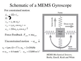
The first simulation model • Due to plane symmetry only half of the structure was simulated. • The package was treated as if mounted on a PCB (ideal heat-sink). • Convection was neglected. • P=1W applied on the chip.
Steady-state results by ANSYS ANSYS simulation, reduced order modeling by THERMODEL Transient step-response by ANSYS Corresponding time-constant spectrum calculated by THERMODEL Element values of the identified 3 stage model network: N R [K/W] C[Ws/K] 1 2.89 4.74e-02 27.54 3.12e-02 3 1.62e+01 2.03e-01
SUNRED simulation, reduced order modeling by THERMODEL Transient step-response by SUNRED Corresponding time-constant spectrum calculated by THERMODEL .SUBCKT cauer 1 0 C0 1 6 1.299838e-02 R0 1 2 1.406075e-01 C1 2 6 2.946844e-02 R1 2 3 1.809813e+00 C2 3 6 1.734340e-02 R2 3 4 6.302130e+00 C3 4 6 1.910058e-01 R3 4 5 1.730904e+01 C4 5 0 7.794206e+00 R4 5 0 2.187223e+00 .ENDS cauer SPICE netlist of the model generated by THERMODEL
SUNRED simulation, time-constant spectrum calculated by direct method
Verification by measurement Measured transient step response and the response of the model generated by THERMODEL from the measured data Time constant spectrum extracted by THERMODEL from the measured unit-step response
The package was treated as if mounted on a PCB and the back surface of the PCB was attached to an ideal heat-sink. • Convection was neglected. • P=1W applied on the chip. • lPCB=0.55 W/mK During simulation the conditions of the measurement setup have to be considered to help model verification. Modified simulation model
Transient step response simulated by SUNRED and the response of the model generated by THERMODEL from the measured data Time constant spectrum extracted by THERMODEL from the simulated unit-step response. Even a single RC stage is enough for modeling. SUNRED transient simulation + THERMODEL Loci of main spectrum lines coincide, and the peak temperature is also close to the measured one.
Execution times Tool # of nodes Time-scale Points/decade Run time* [min/decade] ANSYS transient 17823 logarithmic 10 33.3 SUNRED transient 8192 quasi-log 20 20.3 SUNRED direct t.c. 8192 logarithmic 20 313 Comments 1) Note, that the ANSYS runs were done on a DEC AXP 500 MHz computer, while SUNRED was running on a PC with a 200 MHz Pentium processor. 2) In direct time-constant calculation SUNRED can not take advantage some of its algorithmic features which enable a rather quick transient simulation. 3) Run-time of THERMODEL is a few seconds even on PC, it can be neglected with respect to the execution times of the field solvers.
Summary • We propose a method for reduced order thermal modeling of packages: • transient simulation by a field solver followed by model identification with THERMODEL • transient measurement results evaluation by THERMODEL • Only one example was shown here, but we carried out a lot of similar simulations. We realized, that MEMS packages are well described with very simple reduced order models.
THERMAL SIMULATION (FEM, FDM, BEM) THERMAL TRANSIENT MEASUREMENT THERMODEL Library of reduced order models (e.g. in SPICE format) Multi-domain simulation and design systems Summary
Summary • Sensitivity of different sensors are very much dependent on temperature. Thus, simple but accurate behavioral thermal models of MEMS packages are essential. • In sensor design considering thermal characteristics of packages on system level is important. Our reduced order models can be applied to support this.