Download
1 / 24
240 likes | 397 Views
A Thermal Hydraulic Model for Expendable Launch Vehicles. Michael Berglund Delta IV Launch Vehicle Development May 16-17, 2000. Outline. Point 1 - Correlation with Test Data Rocketdyne Thermal analysis DT-1 RCN Point 2 - Design Tool, Test Transient Conditions

E N D
A Thermal Hydraulic Modelfor Expendable Launch Vehicles Michael Berglund Delta IV Launch Vehicle Development May 16-17, 2000
Outline Point 1 - Correlation with Test Data Rocketdyne Thermal analysis DT-1 RCN Point 2 - Design Tool, Test Transient Conditions Point 3 - Common Modeling System Rocketdyne Controls group Point 4 - Good Customer Support New Parts Specified Modeling Hydraulic Systems Using EASY5 Summary of EASY5 Process
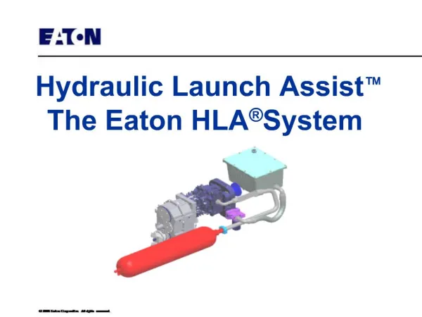
Easy5 Model of RS-68 Hydraulic System Heat Transfer Analysis: EJ Reott • ACTUATOR VERIFICATION • VM fluid output temp TF2VM • FO fluid output temp (corrected) TF2 • Matches MHI Data (error +/- 3.7%)
Easy5 Model of RS-68 Hydraulic System Heat Transfer Analysis: EJ Reott • LINE SEGMENT VERIFICATION • Heat transfer from fluid to wall (BTUH) QFPI • Heat transfer from fluid to wall (corrected) QFPI11 • Wall temp TWPI • Wall temp (corrected) TWPI11 • Matches Calculation (error +/- 0.4%)
Fluid Temp Rise Across OrificeTVC1, TVC2, RCN • EASY5 model: oil temp rise across orifice results: • T = 76°F • Hand Calculations: Oil temp rise across orifice (same conditions) results: • T = 75.9°F
Development Test Models (major assumptions) • Development Test Models • DT_RCN (boundary conditions, spring force) • DT_TVC (boundary conditions, spring + constant force) • DT_Breadboard (valves simulating flow demand for all actuators, single valve representing all 4 engine valves) • DT_System (TVC, RCN actuators included, single valve representing all 4 engine valves) • Hydraulic_System (same as DT_System but with engine valves from Rocketdyne)
RCN Velocity and Stroke EASY5 DT-1 RCN
DT-1 RCN EASY5
DT-1 RCN & Model Correlation DT-1 RCN EASY5
Rocketdyne Received and integrated Rocketdyne’s EASY5 model into CBC EASY5 model Controls Group Common Modeling System
New Components • Found in New EASY5 Library • AD (accumulator with an inlet and outlet), Qin, Qout for both fluid and gas, EFX heat flux • PI - Pipe with heat flux • VO - Volumes with heat flux
EASY5 New Components • New Parameters: EFX and QIN • EFX defines additional energy flux into the volume wall. EFX units are BTUH/in2. • QIN defines additional heat generated internally within the fluid. QIN units are BTUH
Conclusions • EASY5 • Test correlation • Design tool, test transient conditions • Common modeling system • New parts specified • Recommendation: Continue to use EASY5 to model hydraulic system
Modeling Hydraulic Systems Using EASY5 • EASY5 Process • Building a Model
EASY5 Process • Define system and the EASY5 model objective • Build Model by Placing and Linking the Components in the Correct Sequence (use only default or port connection method) • Create an Executable File • Find an Initial Operating Point (All Time Derivatives = Zero) • If the Model Equations Converge, Run a Simulation • Plot Any Output As a Function of Time
Building the Model • Start with simple foundation model, ie, valves for actuators, volumes instead of accumulators, no tabular functions, average values • Run to see if results make sense, check with other team members (in the ball park values) • Build on model, make more complex if preliminary model checks out • Make thermodynamic model as simple as reasonably possible because of potentially large simulation times
Actuators Approximated byMetering Valves Similar to Breadboard Development Test set-up