Download
1 / 36
360 likes | 439 Views
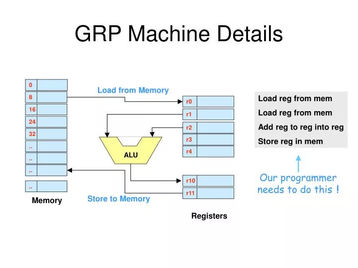
Load from Memory. r10. r11. r0. r1. r2. r4. r3. 0. 8. 16. 24. 32. ALU. Store to Memory. Memory. Registers. GRP Machine Details. Load reg from mem Load reg from mem Add reg to reg into reg Store reg in mem. Our programmer needs to do this !. 0 65. 0 1 1 0 0 1 0 1.

E N D
Load from Memory r10 r11 r0 r1 r2 r4 .. r3 .. 0 8 16 24 32 .. .. ALU Store to Memory Memory Registers GRP Machine Details Load reg from mem Load reg from mem Add reg to reg into reg Store reg in mem Our programmer needs to do this !
0 65 0 1 1 0 0 1 0 1 8 43 0 1 0 0 0 0 1 1 16 24 32 Programs are Numbers Let’s consider a spreadsheet cell which adds two numbers x + y. This cell and its instruction is in memory. 1. Application But it is REPRESENTED in different ways 4. Instructions in memory are just numbers 2. High Level Language 5. Memory stores these as bits w = x + y 3. Assembler Instructions 6. Onto the bus wires as signals load reg from mem add reg to reg into reg
Let’s build a Computer • Let’s take a RISC. What do we need ? • Memory • Registers • ALU • Control Circuits • A programming language • A good Name - Simple Although Meaningful
0 X Y X Code Memory 1 r0 Y r1 r2 W mdr PC mar 7 W What’s needed to build Sam-4 ? Arithmetic – Logic Unit to do the maths business Data memory to hold source and results of our work Registers to hold results of computations Data Memory Code Memory – to store the program
add 0 load 4 add 8 store 12 halt Code Memory PC = 4 Program Memory Data out Memory stores program instructions at a sequence of byte addresses. Each instruction is 32 bits, so the addresses increment by 4 bytes. Here the Program Counter input address 4 to the memory which reads out the data word (32 bits) at address 4. This is the inst- ruction ‘add’ Address in
X Y X r0 Y r1 r2 W W Registers, Registers 1. Registers Store data at addresses. Yep, that’s Memory ! 2. There are TWO read ports (X and Y) where data can be simultaneously read out of the reg file. 4. The addresses for the read ports (X and Y) and the write port (W) come in here. 3. Multiport Registers have an input port (W) where data is send to be written into the register file.
0 1 mdr mar 7 Data Memory The Memory Data Register (MDR) is a parking place for data coming and going from the memory. Here’s the memory The Memory Address Register holds the address of the data location selected for read or write e,g, 7 7
Instruction reg X Y 0 X r0 1 Y r1 Code Memory r2 mdr W Data Memory ALU mar 7 W Here’s Sam
Code Memory The Instruction Register Loaded with the instruction, the IR decodes this into bits which drive the CPU digital logic circuits add 2 1 3 Add r2,r1,r3 2 1 3 add Electronic Wires
Instruction Encoding Example destination All Sam’s instructions take up 32 bits. opcode Source regs Sam’s instructions start with the opcode then the destination reg- ister then the source register rd <- rs + rt e.g. add r3, r1, r2 means r3 = r1 + r2 First 6 bits for the opcode. 3 2 1 Nr of Bits 6 5 5 5 11
Fetch-Execute Cycle 1. Fetch instruction from memory 5. Write back results to registers r3 <- ALU add r3,r2,r1 4. Do any Memory Access 2. Decode the opcode and read any registers None needed ALU <- r1 ALU <- r2 3. Do any ALU operations ALU add Get contents of address 1
Example ld r0 , [1] ld r1 , [2] add r2,r1,r0 st r2 , [7] Load r0 with data at address 1 Load r1 with data at address 2 Add r0 and r1. Put result in r2 Store r2 in memory address 7 Note each of these instructions runs through 5 steps of its own F-E Cycle
1. Instruction Fetch Ld 0 1 X Y 0 X Ld r0,[1] r0 1 Y r1 Code Memory r2 mdr W Data Memory ALU mar PC = 0 7
2. Decode, Reg Ops Ld 0 1 X Y 0 X Ld r0,[1] r0 1 Y 1 r1 Code Memory r2 mdr W Data Memory ALU mar PC = 4 7 +
3. ALU Operation Ld 0 1 X Y 0 X Ld r0,[1] r0 1 Y 1 r1 Code Memory r2 1 mdr W Data Memory ALU 1 mar PC = 4 7
4. Memory Access Ld 0 1 X Y 0 0 X Ld r0,[1] r0 1 1 Y r1 Code Memory r2 mdr W Data Memory ALU 1 mar PC = 4 7 7
5. Register Write Ld 0 1 X Y 0 X Ld r0,[1] r0 1 Y r1 Code Memory r2 mdr W Data Memory ALU mar PC = 4 7 W
1. Instruction Fetch add 2 0 1 X Y 0 X add r2,r0,r1 r0 1 Y r1 Code Memory r2 mdr W Data Memory ALU mar PC = 4 7 W
2. Decode, Reg Ops add 2 0 1 X Y 0 X add r2,r0,r1 r0 1 Y r1 Code Memory r2 mdr W Data Memory ALU mar PC = 8 7 W +
3. ALU Operation add 2 0 1 X Y 0 X add r2,r0,r1 r0 1 Y r1 Code Memory r2 mdr W Data Memory ALU mar PC = 8 7 W
4. Memory Access add 2 0 1 X Y 0 X add r2,r0,r1 r0 1 Y r1 Code Memory r2 mdr W Data Memory ALU mar PC = 8 7 W
5. Register Write add 2 0 1 X Y 0 X add r2,r0,r1 r0 1 Y r1 Code Memory r2 mdr W Data Memory ALU mar PC = 8 7 W
ALU ALU Control Path add r2, r1, r3 The add instruction is decoded and produces digital signals which select the + function in the ALU r1 r3 - + Add ! sub r2, r1, r3 r1 r3 The sub function decoded produces different digital signals - + Subtract !
Sam and MIPS are 32 bit 32 bits wide add rd,rs,rt ldr rd,[rs+c] ldr rd,[c]
Nr of Bits 6 5 5 5 Other Arithmetic Instructions destination rd <- rs - rt opcode Source regs Same coding applies to other arithmetic instructions sub r3,r2,r1 and r2,r1,r0 or r5,r1,r2
r9 145 A simple ‘Load’ instruction destination ‘Load into rd the contents of memory at address which is in reg rs.’ Simple! opcode Single source reg ld rd rs unused memory 0 2. Load the data into r9 1 ldr r9 , [r1] 2 3 3 145 1. Let’s say have already loaded r1 with 3 4 115 5 231 2. Get data from mem at addr r1 (=3) 6 69 7 145
0 1 2 3 145 r9 231 4 115 5 231 6 69 7 A more complex ‘Load’ Load register rd with the contents of memory which you find at address r1 + c. destination opcode Source ldr rd rs constant c memory ldr r9 , [r1 + 2] 3 + 2 The mem address is formed as a sum 5 231
What’s this? 0 1 2 3 145 r9 196 4 115 5 196 6 69 7 … and a ‘Store’ instruction Source destination opcode Note here the data is moved from destination to store. Confusing? Mm. str rd rs constant c 1. Get data from r1 str r9 , [ r1 + 2 ] 3 + 2 5 2. Write it to memory 196
r9 5 ‘Load Immediate’ destination opcode In load immediate we get the constant C immediately following the opcode into the reg. ldi rd Constant C All reference to memory has gone! ldi r9 , 5 5 Load ‘5’ straight into r9
Example ldi rd,C ldi r0,3 ld rd, [rs] ldr r2,[4] ldr rd, [rs + c] ldr r2,[r3 + 4] st rd, [rs] str r0, [r1] str rd, [rs + c] str r6,[r1 + 1] add rd,rs,rt add r3,r1,r1 A Summary So Far … Now it’s time to move on and look in detail at the hierarchy of computer languages – to see the influence on the ISA.
Assembling a Spreadsheet Excel Application The Great Idea here is that the ISA we need at the bottom must serve the grand master at the top, the Application. Main() { int f,g,h; f = g + h; } ld r0, [ g ] ld r1, [ h ] add r2,r0,r1 st r2, [ f ] HLLImple-mentation The ISA must support the HLL implementation Electronics ISA Assembler
Arrays (= Tables) How do we sum the array of numbers in column B? 1. We would use the instruction ld r1,[r0 + B] where B=3, the start address of the array 2. Then we load r0 with 0 then 1, then 2, … to scan down the array Ld r0 , 0 Ld r3 , 0 Ld r1, [r0 + 3] r0 (=0) +3 = 3
Arrays (= Tables) How do we sum the array of numbers in column B? • Increment r1 to get the next data value inc r1 (0 + 1 = 1) • ld r2,[r0 + B] where B=3, the start address of the array but now r- contains 0 Inc r0 Ld r1, [r0 + 3] add r3,r3,r1 Get next cell, lad its value and add it to the sum, in r3
16 ldi r1,10 20 … 24 … 28 bne r2,r1,36 32 addi r3,r3,2 36 … Making Decisions What about SAM? Let’s say we want to add 2 to a number B if another number C is equal to 10 You mean, ‘If C = 10, then add 2 to B’ First load the test number 10 Yep Here’s how we would do it in C Branch around the add if(c == 10) b = b + 2; Branch if not equal r1 r2 to addr 36
0 ldi r0 , 0 4 ldi r1 , 4 8 ldi r2 , 0 12 addi r2 , r2 , 3 16 addi r0 , r0 , 1 20 bne r0,r1,12 Loops Let’s say we want to make the sequence 0,3,6,9,12 and stop. We take 4 steps and each step add 3 x = x + 3 And a register to hold the sum at each step So we need a register to keep track of the number of steps (r0) Branch unless r0 = r1 = 4 r0 r2
.. .. .. .. 0 8 16 24 32 ALU Accumulator Architecure Get 3 from Memory and ADD ! 1. Assume 8 is already in the accumulator. The programmer writes 4 2 3 Add 3 8 Accumulator 8 3 2. The ALU does 3 + 8 = 11 and writes the result back into the accumulator Memory