Download
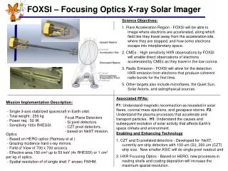
1 / 26
280 likes | 466 Views
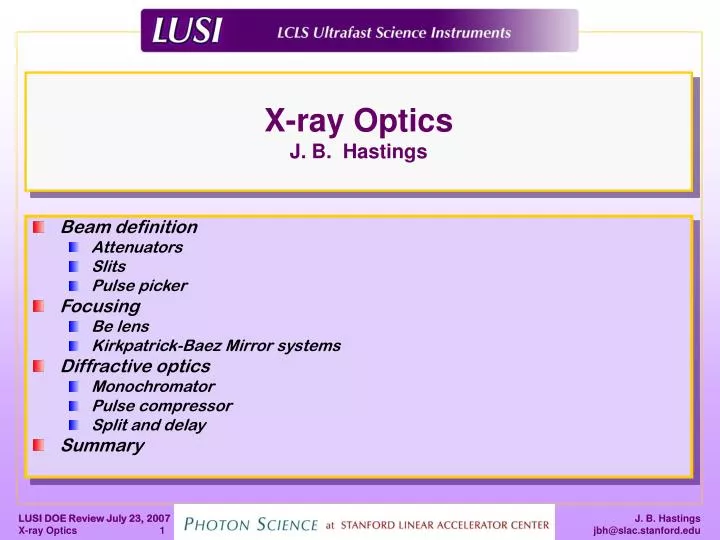
X-ray Optics J. B. Hastings. Beam definition Attenuators Slits Pulse picker Focusing Be lens Kirkpatrick-Baez Mirror systems Diffractive optics Monochromator Pulse compressor Split and delay Summary. LUSI schematic. 1. 3. 2. 5. 4. 6. XPP. XCS. CXI. SXR Imag AMOS (LCLS)

E N D
X-ray OpticsJ. B. Hastings • Beam definition • Attenuators • Slits • Pulse picker • Focusing • Be lens • Kirkpatrick-Baez Mirror systems • Diffractive optics • Monochromator • Pulse compressor • Split and delay • Summary
LUSI schematic 1 3 2 5 4 6 XPP XCS CXI • SXR Imag • AMOS (LCLS) • XR pump-probe Full instrument • XPCS Full instrument • CXI Full instrument • HEDS Beam Transport Offset Monochromator Exp. Chamber Detector LCLS LUSI HEDS (NNSA)
XCS CXI XPP Instruments
XPP XCS Attenuators CXI • Attenuators • Variable, up to 10 6 reduction • High damage threshold (Be or B4C)
XPP XCS Slits System CXI B. Lengeler et al., J. Synchrotron Rad., 6, 1153-1167 (1999). • Slit systems • Variable horizontal and vertical gap from 5 μm – 5 mm • Can withstand full LCLS flux – unfocused • Minimize background scatter from blades
XPP XCS Pulse Picker CXI • Pulse picker • Permit LCLS operation at 120 hz • Single pulses. Useful for samples supported on substrates • Reduced rate ex. 10 hz operation • High damage threshold • Use rotating discs, concept already in use at ESRF
Be Focusing Lenses CXI XPP XCS • Beryllium CRL • > 40% throughput • Positioning resolution and repeatability to 1 µm • Z translation to vary spot size
XPP XCS KB Mirror CXI
KB focusing mirrors • Mirror system (1 µm and 0.1µm KB) • KB mirrors have produced 50 nm focuses of SR (Yamauchi et al., SRI 2006). • Bent plane mirrors – or pre-figured • Achromatic focusing. • Use B4C as coating • Damage resistant • Good reflectivity
KB Pair for 0.1 μm focus Grazing angle 0.2 Deg B4C coating Horz. Mirror 20 cm Vert. Mirror 10 cm Focal spot size (FWHM in microns) Horz: 0.097 Vert: 0.083
LLNL has state-of-the-art surface metrology for the figure, mid- and high spatial frequency ranges R. Soufli, E. Spiller, M. A. Schmidt, J. C. Robinson, S. L. Baker, S. Ratti, M. A. Johnson, E. M. Gullikson, Opt. Eng. 43(12), 3089-3095 (2004). AFM Slope error = 100 rad rms = 17.6 Ǻ rms = 2.7 Ǻ rms
The LLNL DC-magnetron sputtering system can fit multiple large-area substrates in a single deposition 4-mirror and 2-mirror EUV cameras have been multilayer-coated in a single deposition run, achieving optic-to-optic wavelength matching within 1s = 0.010 nm R. Soufli, E. Spiller, M. A. Schmidt, J. C. Davidson, R. F. Grabner, E. M. Gullikson, B. B. Kaufmann, S. L. Baker, H. N. Chapman, R. M. Hudyma, J. S. Taylor, C. C. Walton, C. Montcalm, and J. A. Folta, Proc. SPIE 4343, 51-59 (2001). Underneath view of LLNL chamber lid with 5 sputtering targets
Stress and roughness vs. pressure • Lower pressure films reduce roughness • Also increase stress • Curves shift upwards as thickness grows Favor thinner films grown at higher pressures Higher micro-roughness, minimize risk of delamination
XPP XCS Offset Monochromator CXI • Double Crystal Offset monochromator • Increase longitudinal coherence length (narrow X-ray spectrum) • Multiplexes LCLS beam
Offset Monochromator • Double Crystal Offset monochromator • for 2 µm Si (111) @ 1.5 Å • 85% transmission ,2.5% - Mono beam, 1.3% - Diagnostics beam
XPP XCS Pulse Compressor CXI Parameters for a Laue case pulse compressor for the LCLS.
XPP XCS Split and Delay CXI • Provided by DESY/SLAC MoU • Prototype existing • 1st Commissioning May 2007 • pulse duration < delay < 3 ns • based on Si(511) with 2θ= 90º • E=8.389 keV
Summary • Optical components are conceptually the same as those for SR experiments: slits, attenuators, double crystal monochromators, refractive lens, KB focusing • Optical components are in general not beyond state of the art • Characteristics of the LCLS beam demand extreme precision and damage tolerance: sub-micro radian rotations, B4C coatings • Multiplexing capability relies on thin Si or perfect diamond crystals
Projection optics with diffraction-limited performance have been coated at LLNL during the EUVL program M1 mirror, PO Box 2 39-nm, 3:1 elbows (Patrick Naulleau, LBNL) SES at ALS Normalized film thickness Thickness error (nm) Added figure error = 0.032 nm rms MET camera M2 mirror, MET Set 1 Measured wavefront = 0.55 nm rms K. A. Goldberg et al, J. Vac. Sci. Technol. B 22(6), 2956-2961 (2005) Printed 25 nm equal-line, and 29 nm isolated-line features P. P. Naulleau et al, Proc. SPIE 5751, 56-63 (2005) R. Soufli et al, Appl. Opt. 46 (June 20, 2007) Added figure error = 0.044 nm rms
Reflectometry and scattering beamline 6.3.2 at the ALS synchrotron (LBNL) is operated by CXRO 1-50 nm wavelength range • Beamline Specifications • Wavelength precision: 0.007% • Wavelength uncertainty: 0.013% • Reflectance precision: 0.08% • Reflectance uncertainty: 0.08% • Spectral purity: 99.98% • Dynamic range: 1010 PI = Eric M. Gullikson • Precision Reflectometer • 10 mm 300 mm beam size • 10 mm positioning precision • Angular precision 0.01 deg • 6 degrees of freedom • Sample size up to 200 mm Cross-calibration results are shown between ALS beamline 6.3.2 and the PTB facility at the BESSY synchrotron (Berlin, Germany)
B4C film thickness, roughness and density are verified by fitting of EUV reflectance data B4C film density and composition have been determined through X-ray Photoelectron Spectroscopy and Rutherford Backscattering
1.2.2 X-ray Optics • Double Crystal Offset Monochromator • Motion • 0.02 arcsecond resolution and repeatability (100 nrad) Flexure Stages Piezoelectric Stages
KB Pair for 1 μm focus Grazing angle 0.2 Deg B4C coating Horz. Mirror 20 cm Vert. Mirror 10 cm Focal spot size (FWHM in microns) Horz: 0.6 Vert: 0.9
XPP focusing optics Lens Mono 190 m 4 m
Be lens calculation for 10 micron focus Focal spot size including diffraction and roughness FWHM in microns: Horiz: 12.0 Vert: 10.1 http://www.institut2b.physik.rwth-aachen.de/xray/applets/crlcalc.html