Download
1 / 19
230 likes | 400 Views
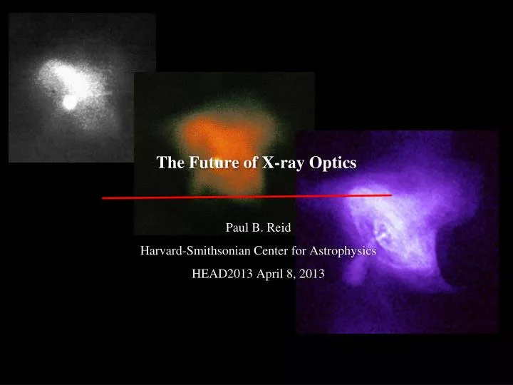
The Future of X-ray Optics. Paul B. Reid Harvard-Smithsonian Center for Astrophysics HEAD2013 April 8, 2013. Where do we need/want to be in 10 – 20 years?. Science goals drive what’s necessary Imaging – high resolution Chandra or better: 0.5 arc sec

E N D
The Future of X-ray Optics Paul B. Reid Harvard-Smithsonian Center for Astrophysics HEAD2013 April 8, 2013
Where do we need/want to be in 10 – 20 years? • Science goals drive what’s necessary • Imaging – high resolution • Chandra or better: 0.5 arc sec • AXSIO / Athena+ / N-Cal / SMART-X Collecting area • > 1 m2 • Large area drives weight – lightweight • < 200 – 400 kg/m2 for reasonable cost and launch vehicle options • Chandra HRMA ~ 1600kg 20,000kg/m2
Imaging resolution vs. collecting area XMM-Newton N-Cal/AXSIO/ Athena+ Resolution (~HPD, arc sec) XMM-Newton Resolution (arc sec) N-Cal/AXSIO Slope ~ 2 Slope ~ 1 Promised Land Chandra Chandra Area (square meters) Area (square meters)
Imaging resolution vs. collecting area N-Cal/AXSIO/ Athena+ Resolution (~HPD, arc sec) XMM-Newton Promised Land Chandra Area (square meters)
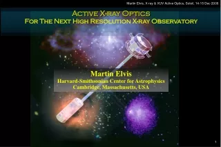
Imaging resolution vs. collecting area Mass α t Area α Mass Distortion α 1/t2 Resol. α Distortion so Resol. α Area2 N-Cal/AXSIO/ Athena+ Resolution (~HPD, arc sec) XMM-Newton Promised Land Chandra Chandra distortion budget = 0.16” Area (square meters)
Imaging resolution vs. collecting area Mass α t Area α Mass Distortion α 1/t2 Resol. α Distortion so Resol. α Area2 N-Cal/AXSIO/ Athena+ Resolution (~HPD, arc sec) XMM-Newton Promised Land Chandra Chandra distortion budget = 0.16” Area (square meters)
Imaging resolution vs. collecting area Mass α t Area α Mass Distortion α 1/t2 Resol. α Distortion so Resol. α Area2 N-Cal/AXSIO/ Athena+ Resolution (~HPD, arc sec) XMM-Newton Promised Land Chandra Chandra distortion budget = 0.16” Area (square meters)
The limiting factors: • Non-deterministic assembly strains limit resolution for thin shells • Chandra budget scaled for 1.5 mm thick shell ~ 15 arc sec RMSD • Don’t want to have to fabricate many mandrels to sub-arc sec accuracy • Chandra mirror surface area ~ 20 sq. meters • 2 sq –m grazing incidence telescope ~ 400 – 500 sq-m surface area
Need to change paradigm regarding stiffness and resolution • Break the relationships between: • Thickness and resolution, or non-deterministic loads and resolution • Assembly loads • Thermal effects • Mirror polishing and resolution • Fortunately, some developmental technologies may do this • Adjustable grazing incidence optics (SAO + PSU + MSFC + JHU) • Differential deposition (MSFC, RXO), Magneto-strictive (NU) • Si-based optics (GSFC, MSFC) • Refractive/diffractive optics ( ? ) • Precision low-force alignment and mounting (SAO, GSFC, MSFC) • Aiming at a couple of arc sec distortions, not 0.1 • Possibility of combining approaches that separately might not work well enough, but together may be good enough.
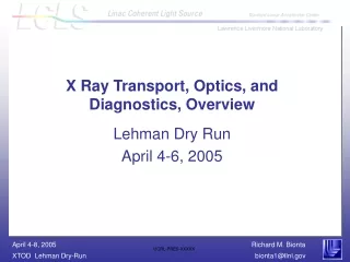
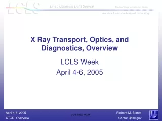
Adjustable X-ray Optics Integrated on-cell strain gauges for remote feedback and on-orbit adjustment. SiO2 layer Top and bottom electrodes 1-2um Piezo layer X-ray reflective coating Glass substrate • Independently addressable piezo cells. • Voltage across top electrode and bottom electrode produces strain in piezo in plane of mirror surface, resulting in localized bending. • Optimizing the piezo voltages after mirror mounting enables correction of fabrication errors and mounting-induced deformations. • Calibrated on-cell strain gauges provide feedback on cell strain/deformation, enable mirror figure corrections to be made on-orbit.
Adjustable X-ray Optics Integrated piezo on-cell control electronics for row-column addressing Integrated on-cell strain gauges for remote feedback and on-orbit adjustment. ZnO layer Top and bottom electrodes 1-2um Piezo layer X-ray reflective coating Glass substrate • Independently addressable piezo cells. • Voltage across top electrode and bottom electrode produces strain in piezo in plane of mirror surface, resulting in localized bending. • Optimizing the piezo voltages after mirror mounting enables correction of fabrication errors and mounting-induced deformations. • Calibrated on-cell strain gauges provide feedback on cell strain/deformation, enable mirror figure corrections to be made on-orbit.
Adjustable X-ray Optics Cylindrical 10 x 10 cm2 mirrors made. Models and measurements agree to 11 nm, rms. Metrology noise ~ 20 nm, rms. Final correction requirement ~ 4 nm, rms
Differential Deposition • Differential deposition – inverse of computer controlled polishing. Image courtesy of B. Ramsey,NASA MSFC • Can correct for mounting distortions but may be less time efficient • Cannot correct on-orbit • Can be used in combo with adjustable approach W.W. Zhang, private communication
Silicon Optics Image courtesy of W.W. Zhang, NASA GSFC • Figure low stress high quality Si wafer • Machine/slice away back material • Stress relieve • Cannot correct post-mounting or on-orbit • Can be used in combo with diff. deposition and/or adjustable approaches W.W. Zhang, private communication
Diffractive-refractive X-ray lenses • van Speybroeck (2000), and independently, Skinner (2001): combine diffractive and refractive elements of opposite power, optimize to reduce chromatic aberration = expand energy bandwidth. • Low Z material • Very large collecting area feasible. • - Easy to imagine 1 – 4 sq meters • Resolution ~ 10 micro arc sec. • Very long focal lengths. • - 100 – 1 million km • - LISA-like mission • Very large focal planes for small FoV. • Narrow energy bandwidth at high resolution: ΔE/E ~ 0.05 G.F. Skinner, A.&A, 383, 352 (2002)
The future? • Thin, lightweight mirror technologies that break the thinness/resolution and mandrel/resolution couplings. • Major Advantage: Correct mounting related distortions • Adjustable optics • Differential deposition • Magneto-strictive optics • Major Advantage: Correct on-orbit (thermal, G-release, …) • Adjustable optics • Amenable to implement in combination with other technologies • Differential deposition • Silicon optics • Adjustable optics, magneto-strictive optics • Refractive/diffractive: bandwidth, focal length, focal plane – probably a long way off .
Summary/Closing • Several prospective technologies being actively worked and currently funded via APRAs, internal funds, etc. • No long term funding for long term development! • Message to NASA: “If you want to find a prince, you have to kiss a lot of frogs!” • Several technology posters • 123.26 Gorenstein – diffractive/refractive • 123.27 Zhang – Si • 123.28 Reid - Adjustable • 123.29 Vikhlinin – SMART-X • 123.30 Schwartz – Wolter-I vs Wolter-Schwarschild for SMART-X • Go to PCOS X-ray SAG meeting, Friday 9 – 5:30