Download
1 / 33
330 likes | 441 Views
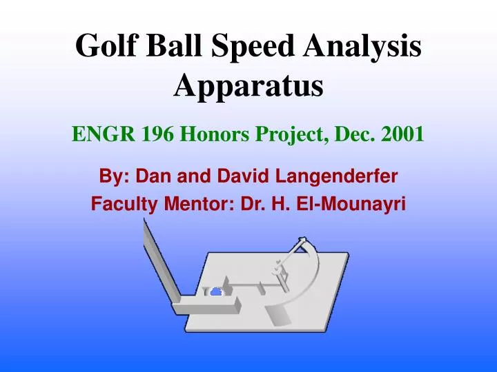
Golf Ball Speed Analysis Apparatus. ENGR 196 Honors Project, Dec. 2001. By: Dan and David Langenderfer Faculty Mentor: Dr. H. El-Mounayri. Original Intent 1 st conceptual design Flaws in 1 st design 2 nd conceptual design Flaws in 2 nd design Motion of apparatus Final design

E N D
Golf Ball Speed Analysis Apparatus ENGR 196 Honors Project, Dec. 2001 By: Dan and David Langenderfer Faculty Mentor: Dr. H. El-Mounayri
Original Intent 1st conceptual design Flaws in 1st design 2nd conceptual design Flaws in 2nd design Motion of apparatus Final design Changes to final design Components Animation at 30° Animation at 25° Graphs of acceleration, velocity, forces, and position Limitations Possible Improvements Outline of Presentation
Original Intent of Project • Find speed of baseball after being hit by a bat. • Slow the measuring apparatus down. • Design apparatus to have relatively no vibration.
Flaws in 1st Design • The parts would have to be big to with stand speed. • The arms used to slow the mechanism down may fly apart. • The joints would not be pin joints, instead they would have to pivot.
Flaws In Second Design • The spring would have a large recoil velocity. • The recoil velocity could injure the player or break his equipment. • The parts would have to be rigid and strong for their size.
Motion of Apparatus • Forces applied by the putter to the ball. • Ball arm pivots on center shaft, while arrow indicates speed of initial impact. • Spring attached to ball arm counteracts the initial impact of the putter. • Ball returns to initial position.
Changes In Final Design(Throughout Process) • Removed the spring from the shaft. • Connected arrow to the ball-arm. • Added half-sphere to the stop.
Components of Final Design • Base Feature • Ball-Arm • Top Retainer • Indicator Arrow • Putter • Spring (Removed from final assembly do to complications in Pro Mechanica).
Assembly • Aligned center axis of base feature with center axis of the ball-arm. • Mated the ball-arm, indicator arrow, and top retainer.
Putter Angle1 = 0.5236 radians Velocity = 0.17244 radians per second Angle2 = 0.4363 radians Velocity = 0.17244 radians per second Ball arm Angle1 = 0 radians Velocity = 0 radians per second Angle2 = 0 radians Velocity = 0 radians per second Initial Conditions
Results • Angular Acceleration • Angular Velocity • Joint Force • Joint Torque • Shoulder Force • Shoulder Torque • Point Acceleration • Point Position • Point Velocity
Angle 25° Angular Acceleration (radians/second2) Time (seconds) Angular Acceleration (radians/second2) Angle 30° Time (seconds) Angular Acceleration
Angle 25° Angular Velocity (radians/second) Time (seconds) Angle 30° Angular Velocity (radians/second) Time (seconds) Angular Velocity
Angle 25° Force (pounds) Time (seconds) Angle 30° Force (pounds) Time (seconds) Joint Force
Angle 25° Torque (pound*inches) Time (seconds) Angle 30° Torque (pound*inches) Time (seconds) Joint Torque
Angle 25° Force (pounds) Time (seconds) Angle 30° Force (pounds) Time (seconds) Shoulder Force
Angle 25° Torque (pound*inches) Time (seconds) Angle 30° Torque (pound*inches) Time (seconds) Shoulder Torque
Angle 25° Angular Acceleration (radians/second2) Time (seconds) Angular Acceleration (radians/second2) Angle 30° Time (seconds) Point Acceleration
Angle 25° Distance (radians) Time (seconds) Angle 30° Distance (radians) Time (seconds) Point Position
Angle 25° Angular Velocity (radians/second) Time (seconds) Angle 30° Angular Velocity (radians/second) Time (seconds) Point Velocity
Limitations • Scale is not calibrated. • Indicator arrow does not help golfer find velocity, distance, or force. • Linear spring may affect results. • Ball-arm hits support for scale. • Motion never stops.
Possible Improvements • Different source of resistance. • Move support for scale.