Download
1 / 18
210 likes | 452 Views
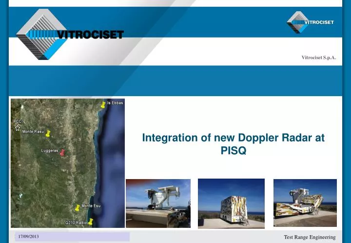
Integration of new Doppler Radar at PISQ. Turn key Project . Installation and Integration into the PISQ test range Renovation of 4 radar sites Radar Installation and operative integration 2 ea MFTR-2100/45-42 in mobile configuration 2 ea MFTR-2100/45-45 in fixed configuration

E N D
Turn key Project • Installation and Integration into the PISQ test range • Renovation of 4 radar sites • Radar Installation and operative integration • 2 eaMFTR-2100/45-42 in mobile configuration • 2 ea MFTR-2100/45-45 in fixed configuration • Radar Data, Video, voice, etc communication between the 4 sites and PCC • Installation of COD @ PCC • Update of PISQ C2 system for receiving data from Weibelradars • T3-Remote Operation Center for all radars at PCC • Assistance after installation of each system
Radar Site Predisposition – Construction • Update of present concrete platform to house radar • Shelter Platform construction • Fence removal and new set-up Electrical works • Power generation system with 2 100 KVA diesel generator in parallel configuration (remotely controlled over LAN) • Installation of an autonomous photovoltaic system • Lightning protection system for direct strike Video surveillance and anti intrusion Cover for Fixed Radar
OPERATOR SHELTER The shelter is equipped as follows: • Three-bay operator console • Air conditioning unit • Rack containing TLC equipments • Power distribution panel • Operative lights and emergency lights • Two doors (main and secondary) • Extensible pole for radio link (only for mobile radars)
TV – Tracker console The TV-Tracker main components are : • Workstation with IMAGO XG video tracking engine and IRIG receiver • Workstation to interface the tracker with other system • Joystick • Video tracking camera The TV-Tracker System will include: • Zoom Color camera with optics (specific for video tracking) • Video signal converters to send videos via optical fiber • Plate to adapt the cameras to the radar pedestal with alignment mechanism • Camera control interface to manage camera parameters
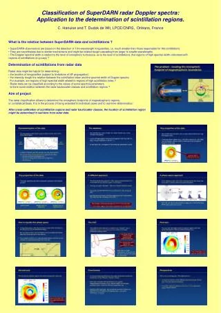
TV – Tracker main interface Designation and Primary target data Angulardiagrams Status control FOV-BW Comparison Real time control command Radar and video targets data Camera parameters control Operative video Imago parameters control Radar information Trackingalgorithmselection
The graphical section of bay 3 include several re-sizeable windows. The functions and displays available are: Window for displaying the PISQ operational scenario Area dedicated to the alphanumeric representation of the time and position data for the primary target under tracking Area dedicated to indicating the radiation blanking zones. Area dedicated to representing the radar working parameters Area dedicated to the representation of diagnostic information (communication channel status and GPS/IRIG synchronisation status) and the status of the processes for the peripheral middleware. Boresight console
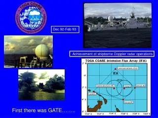
Interpolation of angular errors Boresightconsole: Star Calibrationprocess Star Calibration The Star Calibration System include: • Fixed FOV optics with monochrome GigaE digital camera specific for star calibration • Optical target board installed in a different PISQ site • Plate to adapt the cameras to the radar pedestal with alignment mechanism • Camera control interface to manage camera parameters • Helps to eliminate pointing errors made by radar on target tracking • Errors are obtainedcomparingnominal star position and measured star in Azimuth and Elevation • Stars position are used as known targets • Saves a sufficient amount of static error samples and applies a software correction as a function of angular position of the antenna • Interpolates the static pointing errors to obtain an errors array
Star-Calibrationapplication Star Calibration • System uses a star database to send stars position to the Radar • The radar points the star making an error in azimuth and elevation • Pointing Errors are associated to Az/El positions • Error values are interpolated to obtain a dense correction table for azimuth and elevation sweep. • Real Time Software routine performs angular correction during the Radar motion.
Boresight console: Middleware • The middleware software has the function to allow data exchange between the RTP-2100 and the C2. It is a Real Time system that allows data communication among all the units of the system • It’s main purpose is to elaborate tracking data (coming either from the radar or video tracker) and to send the C2 slaving data to the RTP-2100 • It provides to the BoresightBay, data coming both from the radar and from the PCC to be graphically presented to the local operator. • It provides to the TV-Tracking bay, data coming from the radar
Middleware software • Vitrociset will develop new software components to build the interface between the PISQ’s Command and Control System and the Radar control systems.
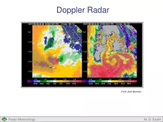
T3 Capacity: system architecture • Remote Control of Doppler radar position (Monte Rasu, Monte Esu, Is Ebbas and Q210) • 2 racks located at the PCC in Perdasdefogu: each one contains 6 workstations, 3 for radar • ICP 2100 : with installed the Wintrack software • TV-Tracker: with installed the TV-Tracker software • Boresight: with installed the Boresight software and T3 remote device control software. • Policy to give arbitration priority between local and remote control. ( normally the priority always be given to the local one.)
T3 Capacity: network architecture Mobile radar connection to the PISQ LAN
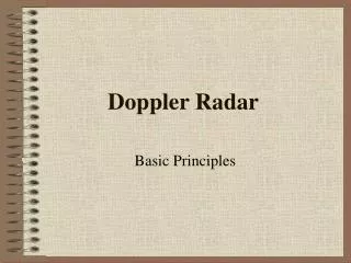
T3 Software interface T3 software startingwindow Remote control of console UPS management window Remote powering of the radar
Vitrociset Contact Details Mr. Danilo PANICO Defence and Homeland Security Vice Director Ph.: +39.06.8820.2207Mob.: +39.335.6351103E-mail: d.panico@vitrociset.itwebsite: www.vitrociset.it Mr. Pietro ANDRONICO Defence and Homeland SecurityAir Force and Test Range Account ManagerPh.: +39 070 8606459 mob.: +39 335 201901E-mail: p.andronico@vitrociset.it Website: www.vitrociset.it