Download
1 / 110
1.11k likes | 1.28k Views
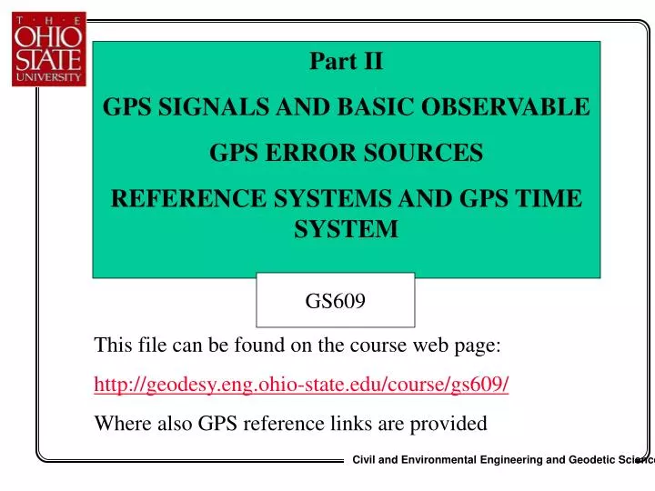
Part II GPS SIGNALS AND BASIC OBSERVABLE GPS ERROR SOURCES REFERENCE SYSTEMS AND GPS TIME SYSTEM. GS609. This file can be found on the course web page: http://geodesy.eng.ohio-state.edu/course/gs609/ Where also GPS reference links are provided. GPS Satellite System 24 satellites

E N D
Part II GPS SIGNALS AND BASIC OBSERVABLE GPS ERROR SOURCES REFERENCE SYSTEMS AND GPS TIME SYSTEM GS609 This file can be found on the course web page: http://geodesy.eng.ohio-state.edu/course/gs609/ Where also GPS reference links are provided
GPS Satellite System 24 satellites altitude ~20,000 km 12-hour period 6 orbital planes inclination 55o
GPS Time System Precise time measurement is behind the success of GPS • GPS uses its own time system that is based on the atomic time scale • Basic units: second of the week (second since the beginning of the week) and a week number • The initial GPS epoch (week 0) is 0h UTC of January 6, 1980 • Universal Coordinated Time (UTC) is the time scale based on atomic second that corresponds to Greenwich time, and is the basis for most radio time signals and legal time systems
Time Systems • There are three basic time systems that can be defined as follows: • - rotational time (sidereal and universal (solar) times based on the diurnal rotation of the Earth that is not uniform) • -dynamical time, defined by the motion of the celestial bodies in the Solar System; it is the independent variable in the equations of motion • - atomic time, based on the electromagnetic oscillations produced by the quantum transitions of an atom with the basic unit being an atomic second, defined as the duration of 9192631770 cycles of radiation corresponding to the transition between two hyperfine levels of the ground state of cesium 133
A basic unit of atomictime, based on the electromagnetic oscillations produced by the quantum transitions of an atom is an atomic second • atomic second is defined as the duration of 9192631770 cycles of radiation corresponding to the transition between two hyperfine levels of the ground state of cesium 133
Time Systems • Since TAI (atomic time) is independent of the Earth’s rotation, the concept of Coordinated Universal Time (UTC), that is in some prescribed way connected to the rotational time, was introduced in 1961, taking advantage of the stability, predictability and almost immediate accessibility of TAI. • UTC is based on the atomic second, thus its rate is uniform. Also, its epoch is manipulated accordingly so that the difference between the time based on Earth diurnal rotation and UTC is maintained on a level less than or equal to 0.7 s. • For that purpose UTC is modified by introducing a leap second, when required, e.g., on December 31 and/or June 30. As a result, UTC and TAI always differ by an integer number of seconds that can change only every year or one-half year
GPS Time System • Since UTC is altered to keep it synchronized with the rotational time (based on Earth rotation rate), the difference (in seconds) between UTC and GPS time grows • Consequently, what you see on most of GPS receiver displays is the GPS time, which is close to UTC (Greenwich time), which is 5 hours ahead from our time zone • One can usually set up the receiver to display local time if needed
GPS Time System • The Global Positioning System (GPS) experienced the first rollover of its internal clock, termed the End of Week (EOW) Rollover, on August 21, 1999 • The EOW rollover exists because the largest increment for counting GPS system time is one week, and weeks are accumulated in a 10-bit register • GPS time started Jan. 6, 1980 with week "0000" and continued until 23:59:47 Universal Time Coordinated (UTC), Aug. 21. • After the rollover, the GPS clock reset itself to "0000." This was the first EOW rollover since the GPS constellation was established.
continuous signal transmit fundamental frequency 10.23 MHz almost circular orbit (e = 0.02) at least 4 satellites visible at all times from any point on the Earth’s surface (5-7 most of the time) GPS Satellite System
GPS - Major Components • Space Segment - responsible for satellite development, manufacturing and launching • Control Segment - continuous monitoring and controlling the system, determining GPS time, prediction of satellite ephemeris and the clock behavior, as well as updating the navigation message for every satellite • User Segment - numerous types of GPS receivers, providing navigators, surveyors, geodesists and other users with precise positioning and timing data
GPS Operational Modes • Precise Positioning Service (PPS) - only for authorized users, provides 2D point positioning accuracy of about below 10 to 20 m (real-time), and 3-5m for static (abut 1 hour) observation • Standard Positioning Service (SPS) - available for numerous civilian applications, provides 2D point positioning accuracy of about 40 m, and 3D accuracy of about ~70 m (much worse under SA); • However, the currently achievable accuracy, even with a hand-held receiver, is • Horizontal Accuracy (50%) - 4 meters • Vertical Accuracy (50%) - 10 meters • Horizontal Accuracy (95%) - 9 meters • Vertical Accuracy (95%) - 22 meters
Restricting the Accuracy of the Standard Positioning Service Department of Defense (DoD) has established a policy for the implementation of Selective Availability (SA) and the Anti-Spoofing (AS) for the GPS signal to limit the number of unauthorized users and the level of accuracy for nonmilitary applications. This results in the degradation in the positioning performance and, in general, complicates the solution strategy. Under AS, the P-code gets encrypted by adding (modulo 2 sum) a W-code, which results in the Y-code, not known to the civilian users.
The fundamental frequency of GPS signal • 10.23 MHz • two signals, L1 and L2, are coherently derived from the basic frequency by multiplying it by 154 and 120, respectively, yielding: • L1 = 1575.42 MHz (~ 19.05 cm) • L2 = 1227.60 MHz (~ 24.45 cm) • The adaptation of signals from two frequencies is a fundamental issue in the reduction of the errors due to the propagation media, mainly, ionospheric refraction and SA
Two carrier frequencies (to remove ionospheric effects) L1: 1575.42 MHz (154 10.23 MHz) wavelength - 19.05 cm L2: 1227.60 MHz (120 10.23 MHz) wavelength - 24.45 cm GPS Signals
New GPS Signal FOR Civilian Users • Planned for Block IIF satellites (2005) • L5: 1176.45 MHz (115 10.23 MHz) • wavelength – 25.5 cm • Signal L2 will remain a civilian signal as well
GPS Signals • Carrier L1 and L2 • P-code (precise/protected code) on L1 and L2 • (under AS policy encrypted with W-code leading to Y-code, which is not directly accessible to civilian users) • C/A – code (clear acquisition) on L1 • The fourth type of signal transmitted by GPS satellites is the broadcast message (navigation message) on L1 and L2 (identical)
Code modulation (sequence of binary values: +1 or –1) L1: P1 & C/A code, navigation message L2: P2 code, navigation message P-code frequency - 10.23 MHz (i. e., 10.23 million binary digits or chips per second) P-code repetition rate: 266.4 days, 7-day long portion of the code are assigned to every satellite; codes are restarted every week at midnight from Saturday to Sunday. P-code “wavelength” - 29.31 m C/A-code frequency - 1.023 MHz (i.e., 1.023 million binary digits or chips per second; codes are repeated every millisecond) C/A-code “wavelength” - 293.1 m GPS Signal Structure 1/2
How do we get the numbers right? • Assuming 1.023 MHz frequency for C/A-code, and repetition rate of 1 millisecond: • 1,023,000 Hz * 10-3 sec = 1023 bits (or chips); this is the length of the C/A code • For 1023 chips in 1 millisecond we get separation between two chips equal to (roughly) 1 microsecond • 1 microsecond separation between the chips corresponds to ~300 m chip length (for 300,000 km/sec speed of light) • Check it out the same way for the P-code!!!
GPS Signal Structure 2/2 • P-code spectrum has a bandwidth of 20 MHz, which corresponds to a resolution of 1 nanosecond i.e. ~ 30 cm • for good signal-to-noise ratio • Thus the accuracy of single P-code range measurement is assumed at ~30 cm level • C/A-code spectrum has a bandwidth of 2 MHz, which corresponds to a resolution of 10 nanosecond i.e. ~ 300 cm • for good signal-to-noise ratio • Thus the accuracy of single C/A-code range measurement is assumed at ~3 m level
GPS Signal Structure • The epochs of both codes are synchronized • In civilian receivers, the short C/A code is acquired first to allow access to the P-code • Carrying two codes on L1 is achieved by phase quadrature • unmodulated L1 carrier is split off and shifted in phase by 90º, then mixed with C-code and then added to the • P-modulated signal – see Figure 7.8 below
GPS Data • Data File • range (pseudorange) measurement derived from code synchronization, • measured phase of carrier frequency L1 and L2, • and (optional) range rate (Doppler) • Navigation Message (broadcast ephemeris) - provides information about satellite orbits, time, clock errors and ionospheric model to remove the ionospheric delay (error) from the observations • Provided in binary-receiver dependent format • Usually converted to RINEX - Receiver Independent Exchange format (ASCII file)
GPS Navigation Message TLM = Telemetry Word HOW = Handover Word (contains Z-count)
TLM, telemetry word – contains a synchronization pattern which facilitates the access to the navigation data • HOW, handover word allows direct access to the PRN code; first the C/A code must be acquired, allowing access to HOW, and then the P-code can be acquired, since C/A code ( allowing then access to navigation message, i.e., the HOW) allows for time synchronization • P-code can be accessed only after the C/A code-supported receiver time synchronization with GPS time through the Z-count • HOW contains so-called Z-count • Z-count is defined as integer number of 1.5-second periods since the beginning of the GPS week, and thus identifies the epoch of a data record in GPS time • If one knows the Z-count, one can acquire the P-code within the next six seconds
GPS Navigation Message (RINEX) 2 NAVIGATION DATA RINEX VERSION / TYPE DAT2RIN 1.00e The Boss 29JUN98 17:59:25 GMT PGM / RUN BY / DATE COMMENT .1118D-07 .0000D+00 -.5960D-07 .0000D+00 ION ALPHA .9011D+05 .0000D+00 -.1966D+06 .0000D+00 ION BETA -.142108547152D-13 -.372529029846D-08 61440 159 DELTA-UTC: A0,A1,T,W 12 LEAP SECONDS END OF HEADER 3 97 10 10 18 0 0.0 .605774112046D-04 .352429196937D-11 .000000000000D+00 .760000000000D+02 .494687500000D+02 .448018661776D-08 .220198356145D+00 .264309346676D-05 .244920048863D-02 .842288136482D-05 .515366117668D+04 .496800000000D+06 .335276126862D-07 -.790250226717D+00 -.372529029846D-07 .951777921211D+00 .211531250000D+03 .259765541557D+01 -.819891294621D-08 .160720980388D-10 .100000000000D+01 .926000000000D+03 .000000000000D+00 .700000000000D+01 .000000000000D+00 .139698386192D-08 .588000000000D+03 .490320000000D+06 6 97 10 10 15 59 44.0 -.358093529940D-06 .000000000000D+00 .000000000000D+00 .220000000000D+02 .526250000000D+02 .438268255632D-08 -.281081720890D+00 …………………….
Orbital (Keplerian) Elements • semimajor axis, a • eccentricity, e • right ascension of the ascending node, o • argument of perigee, • inclination, io • mean anomaly, Mo Algorithm for computing satellite coordinates from broadcast ephemerides is given in GPS Interface Control Document ICD-GPS-200 (see also enclosed hand out) ascending node
GPS Observation File Header (RINEX) 2 OBSERVATION DATA RINEX VERSION / TYPE DAT2RIN 1.00e The Boss 29JUN98 17:59:19 GMT PGM / RUN BY / DATE Mickey Mouse CFM OBSERVER / AGENCY 5137 TRIMBLE 4000SSI Nav 7.25 Sig 3. 7 REC # / TYPE / VERS 0 4000ST L1/L2 GEOD ANT # / TYPE ____0001 MARKER NAME ____0001 MARKER NUMBER 557180.9687 -4865886.9211 4072508.3413 APPROX POSITION XYZ 0.0000 0.0000 0.0000 ANTENNA: DELTA H/E/N 1 1 0 WAVELENGTH FACT L1/2 4 L1 C1 L2 P2 # / TYPES OF OBSERV 1 INTERVAL 1997 10 10 15 13 5.000000 TIME OF FIRST OBS 1997 10 10 16 38 8.000000 TIME OF LAST OBS 8 # OF SATELLITES 3 1598 1603 1504 1504 PRN / # OF OBS 6 4051 4051 4051 4051 PRN / # OF OBS 9 4208 4212 4150 4150 PRN / # OF OBS ……………………… (rest of the SV is given here)………………………………… PRN / # OF OBS END OF HEADER
GPS Observation File (RINEX) 97 10 10 15 13 6.000 0 5 6 10 17 23 26 0.000215178 -331628.90610 21627234.69600 -258412.19950 21627239.86440 -330564.59210 23839375.76600 -264155.63150 23839382.29440 -344922.28510 20838559.61800 -268770.84150 20838564.48140 -344734.12710 22476960.02400 -268624.54850 22476965.59140 -338016.17810 20319996.64100 -263389.71350 20320000.46240 97 10 10 15 13 7.000 0 5 6 10 17 23 26 0.000215197 -329205.73500 21627695.91400 -256524.01640 21627700.98840 -327788.16700 23839904.12500 -261992.18640 23839909.89140 -346924.68000 20838178.43000 -270331.14940 20838183.24640 -346674.25800 22476590.73400 -270136.33740 22476596.25440 -337719.08000 20320053.10100 -263158.20940 20320056.88740 97 10 10 15 13 8.000 0 5 6 10 17 23 26 0.000215216 -326782.19000 21628157.18700 -254635.54040 21628162.34340 -325011.83600 23840432.60100 -259828.81640 23840438.14440 -348926.80400 20837797.46000 -271891.24440 20837802.31240 -348614.34600 22476221.42900 -271648.09340 22476226.99540 -337421.42500 20320109.74100 -262926.27040 20320113.51540 ………………………………………………………………………………. continues
RINEX 2 description: http://www.ngs.noaa.gov/CORS/Rinex2.html http://lox.ucsd.edu/GPSProcessing/Pythagoras/rinex.html
GPS Receiver Multiple channels Antenna and Preamplifier Control and Interface unit Code tracking loop RF Micro-processor Data Storage Carrier tracking loop Power Supply Unit
GPS Receiver: Major Components • Antenna and preamplifier • The GPS receiving antenna detects an electromagnetic signal arriving from a satellite, and after a bandpass filtering, which provides adequate filter selectivity to attenuate adjacent channel interference, and initial preamplification, it transfers the signal to the RF section for further processing by the receiver electronics. • A typical GPS antenna is omnidirectional (azimuthal-plane), thus having essentially non-directional pattern in azimuth and a directional pattern in elevation angle. • As the GPS signals are transmitted with right-hand circular polarization, all GPS antennas must also be right-hand polarized. • It is mandatory for a GPS antenna to maintain high sensitivity (high gain) due to the relative weakness of the incoming signal (gain is a measure of the ability to concentrate in a particular direction the power accepted by the antenna) • Preamplifier boosts the signal level before feeding it to the receiver’s RF front-end section
The physical (geometric) center of the antenna usually does not coincide with the phase center (the electrical center) of the antenna – a point, to which radio signal measurements are referred. • The phase centers for L1 and L2 generally do not coincide, • To avoid problems: always align the leveled antennas in the same direction (local North), which results in cancellation in both length and orientation of the offset between physical and phase centers, when the same type of antenna is used at both ends of a short baseline. For longer baselines, where local verticals can no longer be assumed parallel, as well as for mixed types of antennas, this effect would generally not cancelled out. • In this case, a phase center location has to be a part of the data reduction process, as the amount of the phase center offset is known and provided by the antenna manufacturer. • The location of the phase center can vary with variable azimuth and elevation of the satellites and the intensity of the incoming signal. This effect should not, in general, exceed 1-2 cm, and for modern microstrip antennas it reaches only a few millimeters. • Since GPS signal arrives at the phase center (L1 or L2), but most of the time the coordinates of the ground mark are sought, the observations have to be mathematically reduced to the ground mark location, using the antenna height.
GPS Receiver: Major Components • Radio Frequency (RF) section and tracking loops (heart of a GPS receiver ) • delay lock loop (code tracking) • phase lock loop (carrier tracking) • dedicated channel receivers • switching (multiplexing ) receivers • Basic components of the RF section • precision quartz crystal oscillator used to generate a reference frequency, • multipliers to obtain higher frequencies, • filters to eliminate unwanted frequencies, and signal mixers. • The RF section receives the signal from the antenna, and translates the arriving (Doppler-shifted) frequency to a lower one called beat or intermediate frequency (IF), by mixing the incoming signal with a pure sinusoidal one generated by the local oscillator. As a result, the modulation of IF remains the same, only the carrier frequency becomes the difference between the original signal and the one generated locally and is more easily managed by the rest of the receiver
GPS Receiver: Major Components • Major function of RF section • Precorrelation sampling and filtering • Signal splitting into multiple signal-processing channels: thus the processing that follows is identical for each channel • Doppler removal • Generation of the reference PRN codes • Satellite signal acquisition • Code and carrier tracking from multiple satellites • System data demodulation from the satellite signal • Extracting of pseudorange measurement from PRN code • Extracting of carrier frequency measurements from the satellite signal • Extracting SNR information from the satellite signal • Estimating the relationship to GPS system time
Interaction between delay lock and carrier tracking loops (no AS) Delay tracking C/A-code Acquisition P-code Acquisition Code Removal Delay Estimate Signal from RF section Carrier Phase Estimate Coherent Navigation Data Demodulation and Carrier Recovery
GPS Receiver: Major Components • Microprocessor • real-time operations, such as acquiring and tracking of the satellite signal, decoding the broadcast message, timekeeping, range data processing for navigation, multipath and interference mitigation, etc. are coordinated and controlled by a microprocessor • it can also perform data filtering to reduce the noise, position estimation, datum conversion, interactive communication with the user via the control and display unit, and managing the data flow through the receiver’s communication port • Interface/control • designed as keypad display unit, is used to input commands from the user and display real-time diagnostic and/or navigation information, etc. • Data storage • internal microchips, removable memory cards or solid state (RAM) memory • Power supply • AC or DC (internal rechargeable NiCd batteries, or external batteries such as Lithium Ion battery or Sealed Lead Acid batteries )
Techniques to recover L2 signal under AS • We already discussed how a GPS receiver measures the range (or pseudorange) to the satellite by measuring the time delay between the incoming signal and its replica generated by the receiver • Signal synchronization provides the time measure • The PRN code carried by the signal allows to achieve that (if its known; currently, civilians know only C/A code) • C/A code as less accurate allows for an approximate synchronization • But how do we get an access to the precise P-code under AS policy, if the P-code is not known, and thus, the time synchronization scheme will not work?
Reference Systems and Frames (related to GPS)
Reference Systems and Frames • A coordinate system is most commonly referred to as three mutually perpendicular axes, scale and a specifically defined origin • An access to the coordinate system is provided by coordinates of a set of well defined reference points (forming a reference frame) • Coordinate system and an ellipsoid create a datum; ellipsoid must be defined by two parameters (a and f or a and e); ellipsoid must be oriented in space (usually datum and reference system are used as synonyms) • The most common way of representing a position is with a set of three Cartesian coordinates. • Modern systems, especially these derived from GPS observations are Earth-centered, Earth-fixed (ECEF)
National Imagery and Mapping Agency (NIMA), former Defense Mapping Agency created WGS84 – World Geodetic Datum 84 • National Geodetic Survey (NGS) created NAD83 – North American Datum 83 • International Earth Rotation Service (IERS)createdITRFxx, where xx stands for the reference year at which the frame was (re)established or (re)computed • ITRF stands for International Terrestrial Reference Frame • Currently, WGS84 and ITRF practically coincide
What is ITRF ? • The International Earth Rotation Service (IERS) has been established in 1988 jointly by the International Astronomical Union (IAU) and the International Union of Geodesy and Geophysics (IUGG). The IERS mission is to provide to the worldwide scientific and technical community reference values for Earth orientation parameters and reference realizations of internationally accepted celestial and terrestrial reference systems • In the geodetic terminology, a reference frame is a set of points with their coordinates (in the broad sense) which realize an ideal reference system • The frames produced by IERS as realizations of ITRS are named International Terrestrial ReferenceFrames (ITRF). • Such frames are all (or a part of) the tracking stations and the related monuments which constitute the IERS Network, together with coordinates and their time variations.