Download
1 / 58
580 likes | 701 Views
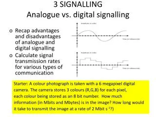
Common Channel Signalling. CONCEPTS OF common channel signalling. MESSAGE TYPES( basic, homogeneous, non homogeneous) How capable of ccs How telephone call is established BASIC ERROR DETECTION METHODS FORWARD AND BACKWARD ERROR CORECTIONS HOW TO FORM CRC(CYCLIC REDUNCY CODE)

E N D
CONCEPTS OF common channel signalling • MESSAGE TYPES( basic, homogeneous, non homogeneous) • How capable of ccs • How telephone call is established • BASIC ERROR DETECTION METHODS • FORWARD AND BACKWARD ERROR CORECTIONS • HOW TO FORM CRC(CYCLIC REDUNCY CODE) • HOW CRC IS REALISED
MESSAGE TYPES • BASIC MESSAGE • HOMOGENIOUS MESSAGE • NON HOMOGENEOUS MESSAGE
Instruction Instruction Data Data Data Variable Fixed Instruction Label Label OPC DPC CIC 14bits 14bits 12bits Basic Message = K1 Message for Homogenous Network = K2 OPC – Originating Point Cord DPC – Destination Point Cord CIC – Circuit Identification Cord
SIO K2 SIO K2 Data Instruction Label 4bits 4bits NO WHY NOT? Message for Non-Homogenous Network SIO - Service Information Octel K2 - Message for Homogenous Network National or International Message User Part Now we are ready with the complete message, can we transmit it just as it is?
IAM ACM ANC CBK
H1 H0 Spare reserved for national use Spare reserved for international and basic national use Spare reserved for national use
Basic concept of message transmission to establish a call IAM B ACM A ANC Ringing current to subscriber “B” n ringback tone to subscriber “A” Speech CBK Variable Node X Node Y H0 H1 IAM (Initial address message) 20 Bits 4 Bits 0001 0001 Dial Number H0 H1 ACM (Answer complete mesaage ) 0100 0001 Fixed (8 Bits) H0 H1 ANC 0110 0001 No Data H0 H1 CBK No Data 0110 0011
HOW THE COMMON CHANNEL SIGNALLING WORKS • ASSUME A CALL IS ESTABLISHED IN A NETWORK WHERE THERE ARE TWO EXCHANGES(EX X & EX Y) ARE CONNECTED WITH 16 PCM SYSTEMS. • THE CALL IS CONNECTED VIA CIRCUIT NUMBER 305. ASSUME P(0) TS16 & P1(1) IS USED FOR COMMON CHANNEL SIGNALLING. • DRAW HOW THE SIGNALS ARE ESTABLISHED BETWEEN THE EXCHANGES(assume the call is establised, and after the call, A keeps the receiver first) • Calculate the total times taken for forward & backward signalling
Need to transfer message between A to B X exchange P0f Y exchange P1f P15f P0b P1b P15b Customer A Customer B
Helicopter View Exchange X Exchange X IAM ( P0f TS16 ) ACM ( P0b TS16 ) ( P9 TS28) RBT ( P0b TS16 ) ANS speaking ( P9f TS28) ( P9b TS28) ( P0f TS16 ) CBR
= (31 * 14) + (30 *2) 494 Number of voice channel for voice communication between X and Y Channel number that we use If we numbered voice channel from 1 to 494 : - Select related TS 30 + 30 =60 305 – 60 = 245 245 / 31 = 7 mod 28 P9 TS28 (PCM no = 9 , TS no = 28) = 305 7 + 2 = 9
Number that we dial = 15904607 IAM K=56 bits Message 8 bits 8 bits Total bits = 150
ACM K=16 bits Message 8 bits 8 bits 8 bits Total bits = 110
ANC K=8 bits Message 8 bits 8 bits 8 bits Total bits = 102
CBR K=8 bits Message 8 bits 8 bits 8 bits Total bits = 102
Conclusion • time for forward message = 2.34 ms • time for forward message = 4.906 ms
Phases of a call Dial Tone Dialing Signaling Answer Speak Release Ring back Tone
ERROR CONTROL • FORWARD ERROR CORRECTION • Detect and correct the error • In unidirectional transmission • BACKWARD ERROR CORRECTION • Detect the error and request for retransmission • In bydirectional transmission
CYCLIC REDUNCY CODE OR FRAME CHECH SEQUANCE • DESIGNED TO DETECT NOISE BURST • ACCORDING TO THE NOISE CHARACTERISTICS A POLYNOMIAL IS IDENTIFIED(N+1 BITS) • SHIFT THE MESSAGE BY N BITS • THEN DIVIDE BY MOULO 2 THE SHIFTED MESSAGE BY THE POLYNOMIAL • GET THE RESIDUAL OF N BITS & SHIFT THE MESSAGE BY THESE BITS AS CRC • AT THE RECEIVER IF THERE ARE NO ERRORS, YOU WILL NOT GET ANY RESIDUAL WHEN YOU DIVIDE THE RECIEVED MESSAGE BY THE SAME POLYNOMIAL
Understanding cyclic redundancy code of error correction(Question)
Hint to answer • Write the polynomial in x • Draw the 1 bit shift registers and the circuit diagram • Write the timing equations for n+1 th step for each output • Sketh the output map– no of columns=no of outputs+steps+input(pl add to the message the no of zeros or crc depending upon the situation, no of rows has to be input+2 • Carryout the timing equation for each step, the last step will give you the output
CRC Input Data • Polynomial:P=11001,P(x)=x4+x3+x0 • X4 X3 X2 X1 X0 • Timing equations • An + In = Dn+1 • Dn = Cn+1 • Cn = Bn+1 • An + Bn = An+1 I + + A B C D
An + Bn = An+1 Cn = Bn+1 Cn+1= Dn+1 An + In = Dn+1
An + Bn = An+1 Cn = Bn+1 Cn+1= Dn+1 An + In = Dn+1
QUESTION • SHOW THE FOLLOWING RECEIVED MESSAGE IS IN ERROR,FOR THE SAME TRASMITTED MESSAGE ie 10010101010100 • Received message:10110100010100 • WRITE THE ERROR MESSAGE EQUATION
ERROR EQUATION • TRANSMITTED MESSAGE + RECIEVED= ERROR MESSAGE • 10010101010100 • 10110100010100 00100001000000 = ERROR MESSAGE E(X)=X6 + X11
INSTANCES WHERE THE CRC IS FAILED TO ANSWER? • THER ARE INSTANCES WHERE THE CRC WILL FAILED TO ANSWER, ONE SUCH INSTANCES WILL BE WHEN THERE ARE ERRORS INTRODUCED EQUAL TO THE POLYNOMIAL
WHEN ERROR MESSAGE IS EQUAL TO THE POLYNOMIAL (EXAMPLE) • ASSUME THE FOLLOWING • TRANSMITTED MESSAGE • 100101010100 • RECEIEVED MESSAGE • 100101001101 • POLYNOMIAL • 1101 • SHOW THAT CRC IS FAILED TO IDENTIFY THE ERROR IN THE MESSAGE?
THOUGH THE RESIDUAL IS 0 THERE IS AN ERROR IN THE RECEIEVED MESSAGE • Hint divide the received message by mod 2 • Then observe that no residuals • Write the error message & compare with the polynomial
TRY A CRC SUM • TRANSMIT MESSAGE • 11001011101 • POLYNOMIAL • 101101 • FIND OUT THE CRC • DRAW THE CIRCUIT DIAGRAM AND SHOW CLEARLY HOW YOU PRODUCE CRC?
How CCITT No:7 works- Study about the layered structure Layer 3 Layer 4 Layer 1 Layer 2 Layer 4 Layer 3 Layer 2 CRC=0 W0 FSN=5,FIB=1 Instructions DATA SIO Label k1 W5 SCF K2 SCF K2 K2 K1 k2 k1 W127 SCF=Sequence control field DPC=st B LABEL CONTENTS BSN=5,BIB=1 SCF Clear W5 OPC|DPC|CIC User Part Signaling Link Link Control Error detection and correction Message type Message handline Signal control Actual message Station A Station B
How reroutine is done? Layer 1 Layer 2 Layer 3 Layer 4 Layer 3 Layer 2 CRC=0 W0 FSN=5,FIB=1 DATA SIO Label k1 W5 SCF K2 SCF K2 K2 k2 DPC=st C k1 W127 SCF=Sequence control field Station A BSN=5,BIB=1 SCF Clear W5 W10 SCF K2 Station B FSN10 ,BIB0 K1 K2 SCF K2 Station C
OSI 7 LAYERS • MUCH MORE VALUE ADDITION HAS BEEN ADDED TO THE MESSAGE PART IN OSI 7 LAYERS • VIRTUALLY THE CCITT NO7 LAYER4 IS BEEN VALUE ADDED , WHILE THE OTHER PARTS REMAINS SAME. • LAYER4 IS BEEN ADDED WITH ANOTHER 4 LAYERS, i.e TRANSPORT, SESSION, PRESENTATION & APPLICATION