Download
1 / 20
220 likes | 428 Views
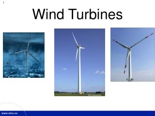
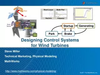
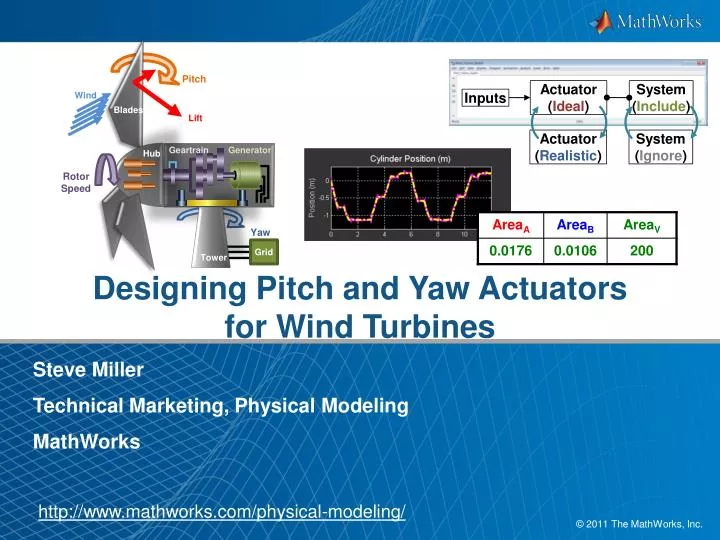
Designing Pitch and Yaw Actuators for Wind Turbines. Pitch. Wind. Blades. Lift. Geartrain. Generator. Hub. Actuator ( Ideal ). System ( Include ). Inputs. Rotor Speed. Actuator ( Realistic ). System ( Ignore ). Steve Miller Technical Marketing, Physical Modeling MathWorks.

E N D
DesigningPitchand Yaw Actuatorsfor Wind Turbines Pitch Wind Blades Lift Geartrain Generator Hub Actuator(Ideal) System (Include) Inputs RotorSpeed Actuator(Realistic) System (Ignore) Steve Miller Technical Marketing, Physical Modeling MathWorks Yaw Tower Grid http://www.mathworks.com/physical-modeling/
Key Points • The ability to easily adjustthe level of model fidelityenables efficient development • Creating reusable models of custom physical elements eliminates redundant work • Accurate parameter valuescan be determined automaticallyusing optimization algorithmsand measurement data Actuator(Realistic) System (Ignore) Actuator(Ideal) System (Include) Inputs
Agenda • Pitch and yaw systems in full wind turbine model • Determining pitch system requirements • Modeling a hydraulic pitch system • Modeling an electrical yaw system • Modeling custom components • Validating models against measurement data
Determine Pitch Actuator Requirements Model: PitchCommand ActuatorForce Control CylinderExtension Problem:Determine the performance requirements for the pitch actuator (force and speed) Solution: Use an ideal actuator and a controller to model the pitch system
Agenda • Pitch and yaw systems in full wind turbine model • Determining pitch system requirements • Modeling a hydraulic pitch system • Modeling an electrical yaw system • Modeling custom components • Validating models against measurement data
Test HydraulicPitch Actuator Design Model: Control Problem:Test a design for ahydraulic pitch actuation systemincluding power failure condition Solution: Use SimHydraulicsto model the hydraulic actuator
Agenda • Pitch and yaw systems in full wind turbine model • Determining pitch system requirements • Modeling a hydraulic pitch system • Modeling an electrical yaw system • Modeling custom components • Validating models against measurement data
Determine Yaw Actuator Requirements Model: TopView Side View Problem:Determine the torque requirements for the yaw actuator Solution: Use an ideal actuator to model the yaw system Yaw RateCmd YawCommand Control Control Torque Limit Rateto 0.5 deg/s Nacelle Yaw Angle Nacelle Yaw Rate
Test Electrical Yaw Actuator Design Model: Problem:Model the yaw actuators in the Simulink environment Solution: Use SimElectronics and SimDriveline to model the yaw actuator
Agenda • Pitch and yaw systems in full wind turbine model • Determining pitch system requirements • Modeling a hydraulic pitch system • Modeling an electrical yaw system • Modeling custom components • Validating models against measurement data
Re ≥ Recr q = Re < Recr Model Custom Physical Components Model: • MATLAB based • Object-oriented • Define implicit equations (DAEs and ODEs) Problem:Create a new physicalmodeling component for use in the Simulink environment using this equation. Solution:Use the Simscape language to model the component.
Extend and Create Libraries • Definethephysicalnetworkportsforthe Simscape block • Reuse existingphysicaldomainstoextendlibraries • Definenewphysicaldomains
Define User Interface • Parameters, default values, units, and dialog box text all defined in the Simscape file (extension .ssc)
Simscape Language: MATLAB Based • Use MATLAB functionsandexpressionsfortypicalphysicalmodelingtasks: • Analyze parameters • Perform preliminary computations • Initialize system variables • Syntax closelyfollowsMATLAB language
Re ≥ Recr q = Re < Recr Create Reusable Components • Equations defined in a text-based language • Based on variables, their time derivatives, parameters, etc. • Define simultaneous equations • Can be DAEs, ODEs, etc. • Assignment not required • Specifying inputs and outputs not required
Agenda • Pitch and yaw systems in full wind turbine model • Determining pitch system requirements • Modeling a hydraulic pitch system • Modeling an electrical yaw system • Modeling custom components • Validating models against measurement data
A B A B AreaA AreaB AreaV T P T Estimating Parameters Using Measured Data Model: Problem:Simulation results do not match measured data because parameters values are incorrect Solution:Use Simulink Design Optimization to automatically tune model parameters
Estimating Parameters UsingMeasured Data • Steps to Estimating Parameters1. Import measurement data and select estimation data 2. Identify parameters and their ranges 3. Perform parameter estimation
Estimating Parameters UsingMeasured Data • Advantages of Simulink Design Optimization • Enables quick and easy comparison of simulation results and measured data to ensure simulation matches reality • Automatic tuning of parameters saves time • Optimization algorithms reveal parameter sensitivity and help improve model parameterization
Key Points • The ability to easily adjustthe level of model fidelityenables efficient development • Creating reusable models of custom physical elements eliminates redundant work • Accurate parameter valuescan be determined automaticallyusing optimization algorithmsand measurement data Actuator(Realistic) System (Ignore) Actuator(Ideal) System (Include) Inputs