Download
1 / 24
240 likes | 367 Views
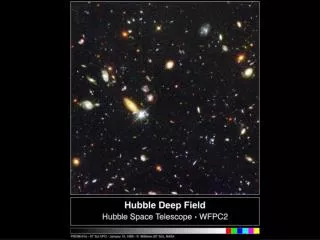
Hubble Ultra-Wide-Field Imager (HUFI). David Leckrone Senior Project Scientist for HST December 16, 2001. HUFI (90 arcmin 2 ). (5.7 arcmin 2 ). (69 arcmin 2 ). (11.3 arcmin 2 ). Field of View. 4K x 4K CCD’s (3). Optical Schematic. M3 Mirror. M1 Mirror. Pupil. Filters, CCD

E N D
Hubble Ultra-Wide-Field Imager (HUFI) David Leckrone Senior Project Scientist for HST December 16, 2001
HUFI (90 arcmin2) (5.7 arcmin2) (69 arcmin2) (11.3 arcmin2)
Field of View 4K x 4K CCD’s (3)
Optical Schematic M3 Mirror M1 Mirror Pupil Filters, CCD Shutter Location M2 Mirror CCD FPA Radial “Pickle” Pick Off Mirror (POM) HST OTA
Geometric ray trace compared to two-pixel and four-pixel width scale-bars shows a well-corrected design.
Optical Performance Diffraction PSF encircled energy @ =632.8 nm for center field and 4 other field positions show that PSF is diffraction-limited and is uniform over full FOV
Instrument Layout Filter Mechanism CCD Heat Pipes Calibration Door Mechanism M3 M1 M1 Corrector Mechanism Shutter Mechanism Pick Off Mirror
Instrument Layout FGS Enclosure Side Optical Bench Strut Point C (Point B Opposite Side) CPL Saddle To AS Radiator Radiator
Instrument Layout M2 FGS Enclosure M2 Support
+V2 SIDE OF HST FGS3 BAY NCS RADIATOR
HUFI Design Features • All-Reflective Design • Four surfaces – one flat, three powered • Well-Corrected Aberrations • Wavefront error 0.0451 to 0.0523 waves rms at 632.8nm • Flat Focal Surface • Requires three 4Kx4K CCD’s similar to ACS and WFC3 detectors • Cooling Via HUFI External Radiator Plus Coupling To NCS Radiator • Replaces FGS #3 Without Compromising Current Pointing Performance • Does Not Interfere With Other Instruments • Amenable to parallel observing • Follow-up observations with WFC3, COS, ACS, STIS
HUFI Scientific Performance • FOV – 90 arcmin2 (8xACS, 16xWFPC2) • Pixel Scale – 0.10 arcsec (same as WFPC2) • Sensitivity – Comparable to ACS in I-band, 5x WFPC2 in I-band • Discovery Efficiency – 8xACS, 80xWFPC2 • SNe Ia Discovery Rate - ~1 per day with follow-up
POTENTIAL OBSERVING STRATEGY • 3-6 Month campaigns dedicated to high galactic latitude fields • Deep exposures with WFC3, COS, ACS broken into multiple visits – HUFI parallel exposures for “free” • SN detected in HUFI fields followed with other HST instruments • STIS spectra for redshifts and classifications up to z=1.2 • WFC3 near-IR images and grism spectroscopy up to 1.7 microns • ACS higher resolution images for host galaxy morphology
200 SNe la 200 SNe la + M = 10%
200 SNe la 200 SNe la + MAP + Ho = 10%
HUBBLE MISSIONS End of Mission SM4 ? SM3B SM3A Wide Field Camera 3 Fine Guidance Sensor Aft Shroud Cooling System Batteries Gyros Advanced Camera Solar Arrays Power Control Unit NICMOS Cooling System SM2 Gyros Advanced Computer Fine Guidance Sensor SM1 Imaging Spectrograph Near Infrared Camera Fine Guidance Sensor Launch! Wild Field Planetary Camera 2 COSTAR Gyros Solar Arrays 1990 1993 1997 1999 2002 2004 2010
RETIREMENT OPTIONS FOR HST • One Shuttle flight allocated to HST after Servicing Mission 4 in 2004 • Current baseline plan is to return HST to the ground in 2010 • Exhibit in National Air & Space Museum • Requires partial disassembly and disposal of multiple pieces in orbit (e.g. solar arrays, external radiators, possibly instruments) • 5 EVA mission • Requires HST to be stable and commandable • Less than 50/50 chance that HST will function to 2010 • Alternative option • “Light” servicing mission in 2007 instead of 2010 • Maximizes probability of zero downtime between HST and NGST • Attach propulsion module to HST for end-of-mission controlled re-entry • Provides possible opportunity for new instrument, e.g. HUFI
9/10/01 HST Reliability Indicator from the Refined Aerospace Corporation Model 1.0 .5 Probability .0 0 1 2 3 4 5 6 7 Elapsed Time - Years Probability of HST Science Operations vs. Time Since Last Servicing Mission
SUMMARY • We’ve identified an instrument design which provides a major increase in FOV compared to prior HST cameras • A systematic campaign should yield ~1 SNe per day with follow up provided by full suite of HST instruments • Flight opportunity requires change in current baseline retirement plan for HST and willingness of Code S to support a new HST instrument
Thermal Block Diagram 90 watts electronics to modified “door radiator” using HPs “New” Radiator/ Door HUFI Radial SI 120 watts to NCS Radiator using HP/VCHP to carry heat from CEB and CCDs 40 watts to AS Existing Inserts NCS Radiator
Power Flow Total estimated power requirement of 250 W HUFI Radial SI 190 watts from NCS Radiator auxiliary power supply 60 watts From HST Diode Box Auxilary Power Ports NCS Radiator