Download
1 / 26
260 likes | 428 Views
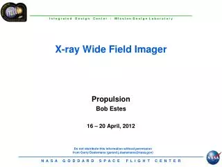
X-ray Wide Field Imager. Orbital Debris and End of Mission Plans Ivonne Rodriguez 16 – 20 April, 2012. Orbital Debris and EOMP Agenda. Orbital Debris Requirements Overview Micrometeoroid Damage Assessment Conclusions Acronym List Backup Material.

E N D
X-ray Wide Field Imager Orbital Debris and End of Mission Plans Ivonne Rodriguez 16 – 20 April, 2012
Orbital Debris and EOMP Agenda • Orbital Debris Requirements Overview • Micrometeoroid Damage Assessment • Conclusions • Acronym List • Backup Material
Orbital Debris Requirements per NASA-STD-8719.14: Most Requirements Do not Apply to L2 Missions (See Backup charts for complete requirements)
Probability of Damage due to Micrometeoroid Environment: General Procedure • The number of impacts, h, is given by: • h = F x A x T, where: • F is the particle flux in impacts/m2/yr • A is the cross-sectional area of the component in m2 • T is the mission lifetime in years. • The probability of penetration is given by: • P = 1-e(-h) • The flux F is obtained from the Grün interplanetary meteoroid flux based on the minimum particle diameter (critical diameter) capable of penetrating the surface under study. • The critical diameter is computed from ballistic limit equations. For this study, the software BLA (Ballistic Limit Analysis) was used to obtain the critical diameter. • In the Grün model, the micrometeoroid (MM) flux is averaged for a year, and is assumed to strike normal to a flat surface in random orientation. • This analysis covers the metering structure, representative components on the bus section, and vulnerability of the instrument from the mirror side.
Increased Damage to Metering Structures with Reduced Thickness • Perforation of Metering Structures • Probability of penetration by micrometeoroids varies with facesheet thickness. Baseline is 1 mm each facesheet; other thickness values are shown for comparison. • Failure is defined as penetration of the two facesheets. • Smallest particle capable of penetrating the structure for the worst case = 0.046 cm diameter (0.0885 cm for baseline 1 mm facesheets). • The following table summarizes the results for a single metering structure, assuming no shielding by other structures: Baseline • If the metering structure is perforated by a micrometeoroid, the highest probability corresponds to a hole diameter of about 6 mm in diameter.
Bus: Propellant Tank and Battery • Propulsion tank and battery box are selected as representative of components located in the bus section. Decks and other panels limit the damage in several directions. For the purposes of this analysis only the flux coming from unshielded directions is taken into consideration. • Failure is defined as penetration of the component wall. • Most of the propulsion tank is exposed to space, shielded by MLI only. This results in a higher probability of failure than in previous studies, were the tanks were enclosed by the bus structure. Typical MLI is not enough to protect a pressurized vessel from hypervelocity impacts. • To reduce the risk of explosion due to particle impacts, add structural panels to cover exposed sections or add flexible shields (See next slide).
If Mass is a Concern, Consider Flexible Shields instead of Solid Shields for Exposed Tank Sections • Multi-Shock shields (MSS) are defined as a combination of four ceramic fabric bumpers followed by either an Aluminum or Kevlar rear wall. • Ceramic bumpers produce higher shock pressures in the projectile than Aluminum, which translates into better projectile breakup. • Fabric ceramic bumpers are more damage tolerant than monolithic (solid) ceramic layers which tend to disintegrate upon impact. • In many cases, fabrics are more suitable for spacecraft shielding applications than solid bumpers. • Increasing the standoff distance (while keeping the layers equidistant between one another) increases the efficiency of the flexible shield. • Reference: Eric Christiansen, Handbook for Designing MMOD Protection, NASA/TM-2009-214785, pp. 66-74.
Thin MSS Can Provide Additional Protection to the Exposed Tanks • For the WFI spacecraft: • A MSS shield with Nextel fabric bumpers and Kevlar fabric rear wall is recommended. • In this case, failure is defined as full penetration of the MSS. • The probability of penetration of a 2-cm thick MSS shield is 0.2% in this case. • The mass of a MSS 2-cm thick covering the exposed tank areas is approximately 0.175 kg for each tank, or 0.525 kg total. • The probability of penetration of a wall behind the MSS (the tank wall in this case) has not been defined experimentally. However, the probability of a particle to even reach the outer surface of the tank is reduced to 0.2% (or lower if a 3 cm or 4 cm MSS is used).
WFI Damage from The Telescope Side • The probability of damage to the filter from particles coming from the mirrors’ side is a separate case from the hardware assessment for the following reasons: • While in the hardware assessment a failure is defined as penetration of a wall or surface, in this case a particle impact to the surface not always produce permanent damage to the instrument. Depending on the size of the particle, the result may vary from a temporary production of bright pixels to penetration of the surface. • It does not involve a direct hit by the particle, but is the result of scattering through the mirrors. • Note that the results depend on the specific mirror configuration. • The particle reaching the instrument might be ejecta produced by the impact with the mirror foil (the MM vaporizes), or the scattered MM after impacting the mirror shell. • The analysis is limited to the particles that reach the instrument through a mirror assembly, which depends on instrument geometry (next slide). Not all particles striking the mirrors may reach the instrument. • Computation of the mirror effective area is based on Carpenter, et al, Effects of Micrometeoroid and Space Debris Impacts in Grazing Incidence Telescopes, from Space Telescopes and Instrumentation II: Ultraviolet to Gamma Ray, Proc. of SPIE Vol 6266, 62663K (2006).
Analysis Assumptions and Equations Mirror effective area based on the probability of an entering particle to reach the instrument: • R1 = front radius of the nth mirror shell’s parabolic mirror. • R2 = radius at the interface between the two hyperbolic and parabolic mirrors. • An = on-axis component of the mirror area. • A = on-axis area of the nest of n mirrors. • a = Minimum scatter angle required to hit the detector or filter. • P(0<θ< a) = probability that a particle is scattered by an angle which is less than some upper limit a. • Phit = probability that a particle will strike the detector or filter. • Anp = on-axis “effective” area for a single mirror shell. • Ap = total on-axis “effective” area for the telescope. • Assumed values: • R2 : Assumed 1mm less than R1. • a: Assumed 0.7⁰ (Swift, XMM) Once the total effective area is obtained, the analysis proceeds as in the hardware section (P=FxAxT).
Probability of Particle Reaching the WFI from the Telescope Side Values for one mirror: Effective area Apfor one mirror: Probability of impact to the instrument from the inside, by particle size, for 3 yrs and 5 yrs (assuming a 3 mm glass or filter over the instrument aperture): • As expected, the probability decreases rapidly with increased size. • High probability of a few impacts by particles in the 1 micron range. However, the expected damage may be limited to a crater of few microns in diameter on the surface. • An impact by a particle of about 0.5 mm is capable of penetrating a 3-mm thick glass. However, the probability for that scenario is very low.
Conclusions and Comments • No issues in terms of orbital debris and end of mission plans. Most requirements do not apply. • Disposal recommendations: give a soft “push” at EOM to help the spacecraft to drift away from L2 and make it easier to prove that the spacecraft will not come back to Earth vicinity. • Each tank is partially exposed to space, not entirely covered by bus structure, making it more vulnerable to impacts from small particles. The probability of damage to one propulsion tank is 12% for 3 yrs and 20% for 5 yrs. • Use Kevlar sheets or Multi-shock shield (MSS) to reduce the probability of damage with minimum additional mass. • The probability of at least one particle reaching the instrument from the telescope side is 69% for 3 years and 85% for 5 years for particles 1 μm in diameter, which is not expected to produce permanent damage to the instrument. Particles capable of producing permanent damage have probabilities << 1% of reaching the instrument from the inside.
Acronym List • BLA – Balistic Limit Analysis • EOM – End of Mission • MM – Micrometeoroid(s) • MSS – Multi-Shock Shield
The Grün MM Flux Model • Gives the flux of sporadic and stream MM averaged for a year. Assumes all impacts are normal to the surface. • Omnidirectional; assumes maximum flux in every direction (Conservative). • Assumes the surface is a flat plate in random direction. In this case, boxes are represented as 5 flat surfaces (one side is attached to the instrument panel) and cylinders as 2D projections (cross-sectional area), excluding the top (protected by radiator) and bottom. • Easy to codify in Excel or other math software. • Less detailed than the most recent MSFC’s Meteoroid Environment Model 1c (MEM R1c), which is directional. • See NASA TM-4527, Section VII for more details on the micrometeoroid environment.
Data Tables and Results, 3 years Particles reaching the instrument through the mirrors:
Data Tables and Results, 5 years Particles reaching the instrument through the mirrors:
4.4 Assessment of Debris Generated by Explosions and Intentional Breakups
4.4 Assessment of Debris Generated by Explosions and Intentional Breakups, cont.
4.7 Survival of Debris From the Postmission Disposal Earth Atmospheric Reentry Option