Download
1 / 17
170 likes | 275 Views
A LAV FEE based readout for the CHOD @ the synchronization run. Mauro Raggi LNF TDAQ WG CERN 9/02/ 2011. Outline. The CHOD detector Does the LAV FEE fits the CHOD requirements? Time resolution Charge resolution Rate during syncronization Possible CHOD readout

E N D
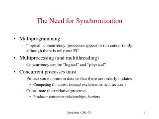
A LAV FEE based readout for the CHOD @ the synchronization run Mauro Raggi LNF TDAQ WGCERN 9/02/2011
Outline • The CHOD detector • Does the LAV FEE fits the CHOD requirements? • Time resolution • Charge resolution • Rate during syncronization • Possible CHOD readout • L0 Q1 trigger at the synchronization run
The CHOD detector A time resolution better than 200 ps per counter was measured from the data during NA48 data taking. 2 planes x 64 counters per plane 128 ch total The typical PM signal from a hodoscope counter was 300mV high and 30 ns long. Dynamic range up to 1V (3MIP)
Why the LAV FEE for the CHOD • CHOD dynamic range (50mV, 1V) • The CHOD dynamic range much smaller to the LAV one • CHOD time resolution • Few hundred of ps time resolution is more than enough during synchronization run • CHOD charge measurement • A precise charge measurement is not needed for the chod • The LAV FEE can give better than ~10% resolution on charge • Maximum tolerable rate • The tolerable rate for single ch of LAV readout chain can exceed 250KHz limited by HPTDC • The 32ch modularity fit exactly the CHOD geometry
LAV FEE working principle Produce a LVDS signal of wdt equivalent to the time the signal is over threshold Clamp the signal Amplify 3 & splitCompare with thr and produce an LVDS Details in G. Corradi, TDAQ WG dec 2010
FEE LAV VME9U CAN in, CAN out Remote Control USB Local Control Vth_H and Vth_L test points and adjust trimmers Sum 1 to 16 Sum 1 to 16 Sums 1 to 4, 5 to 8, 9 to 12, 13 to 16 Sums 1 to 4, 5 to 8, 9 to 12, 13 to 16 Sum 17 to 32 Sums 17 to 20, 21 to 24, 25 to 28, 29 to 32
Online Time slewing correction Exploiting the presence of a double threshold on the LAV FEE board an online slewing correction is possible for the CHOD: Define TL = leading edge time (ns) for the Lower threshold TH = leading edge time (ns) for the Higher threshold T0 = Time of the event (ns) extrapolated to 0 mV (slewing corrected) LTHR = Lower threshold value in mV HTHR= Higher threshold value in mV T0 LThr TL TH HThr
Test beam 2010: LAV time resolution Offline slewing correction applied using V(t) ~ ta e-tbOnly TDC used in the correction 4 mV threshold 210 ps /√[E10E26/(E10+E26)] (GeV) More than enough for the CHOD in the synchronization run! D. Di Filippo, P. Massarotti, T. Spadaro LAV WG dec 2010
Q (pC) ToT (ns) LAV FEE charge performance The charge resolution is very good in a limited range that matches very well CHOD requirement (1-3 MIP range) D. Di Filippo, P. Massarotti, T. Spadaro LAV WG dec 2010
Possible CHOD readout chain Need 4 LAV FEE board (32ch in each)1 TEL62 or even TELL12 TDC boards (SCSII connection)1 LAV Wiener crate (9U J1 only) Each LAV FEE board will house 2 CHOD quadrants (half a plane) Each TDC will house a whole CHOD plane The TEL62 will house the whole CHOD 4xFEE board 1xTEL62
Connections issue • The input of the LAV FEE board is made by DB37 connectors • The output of the CHOD is made by LEMO-00 cable • 2 possible solution: • Build a patch panel with lemo IN connectors in and DB37 out • Build custom patch cables like the one below • Use the same LAV connector
The FEE analog sums on CHOD • One FEE boards serves 32 channels = 1/2 plane • 32 analog outputs cannot all be housed on the board: • (there isn’t enough space on the front panel) • sum 4 slabs analog signals • sum 16 slabs(16 slabs= V2 quadrant amazing!) • Output via Coax 50 W, Lemo-00
L0 trigger with the CHOD • The presence of all CHOD ch in a single TEL62 allows the Q1 logic to be implemented the FPGAs • Each PP FPGA counts the number of hits in a plane (64 ch) • The SL FPGA makes the coincidence horizontal & vertical • The use of the analog sum, a discriminator and a logic unit allow to produce a NIM simplified version of the Q1 that can be used in scaler discr Sum H1 H1 H1&V1 Sum H2 H2 Sum H3 NIM Q1 H3 H2&V2 Sum H4 OR H4 Scalers? H3&V3 Sum V1 V1 Sum V2 V2 Sum V3 H4&V4 V3 Sum V4 V4
Sum16 based simplified Q1 • Using an additional FEE board and TDC we can: • Insert the 8 sum16 (a quadrant) as 8 additional channels in the read out (see fig below). • The Q1 logic in the PP-FPGA is now easy: • CH0&CH4 or CH1&CH5 or CH2&CH6 or CH3&CH7 • Where CH(i)&CH(j) means |T(ch0)-T(ch4)|<10 ns • Use the higerthr in veto to establish if there is more than 1 track in the sum V2CH1 H2CH5 V1CH0 H1CH4 V4CH3 H4CH6 V3CH2 H3CH7
Sum4 based sub-quadrant Q1 • Using an additional FEE board and TDC we can: • Insert the sum4 as 32 additional channels in the read out • The Q1 logic in the PP-FPGA is now improved: • Can give precise localization of track • Can reduce 2 tracks contamination in Q1 V Plane H Plane
Conclusions • The LAV FEE boards seems to fit the requirements for being used as readout for the CHOD during the synchronization run • The analog sums implemented in the FEE board can be used for triggering purpose • Using both FPGAs or NIM electronics • The TEL62 readout provide an easy way of reproducing pre-trigger algorithms
CHOD as L0 supervisor IF TELL1 FPGA is able to generate the LVL0 signal for TTC we can even think of using the CHOD’s TEL62 as backup solution LVL0 supervisor for the synchronization run: Connect LAV and MUV using the Gbit eth implement the logic: Communicate the result to TTC ANTI-A1 TELL62 MUV TELL62 CHOD TELL62 TTC To readout PC