Download
1 / 12
130 likes | 345 Views
EEE342 Sequential Synchronous Machines, State Diagrams and One-Hot coding. Ian McCrum. Sequential machines – flip-flops. We have seen how a flip-flop changes “state” when it is clocked.

E N D
EEE342Sequential Synchronous Machines, State Diagrams and One-Hot coding Ian McCrum
Sequential machines – flip-flops We have seen how a flip-flop changes “state” when it is clocked. The details of the change are determined by the values of the control inputs at the instant of the active edge of the clock. (Quartus flip-flops are controlled by the rising edge of the clock input.) A D-type can either RESET or SET depending on whether its D input is put to a ‘0’ or a ‘1’. BUT the action does not occur until the clock edge. Putting a value on the D input sets up the conditions for a change but the change is SYNCHRONOUS to the clock edge. A B C D E F G H I J K L CLK D Q D changes between B and C but it is not until the clock edge at D that the action to set is taken. Q changes a few nanoseconds after the clock edge (depending on the device)
Sequential machines – flip-flops A T-type can either HOLD or TOGGLE depending on whether its T input is put to a ‘0’ or a ‘1’. BUT the action does not occur until the clock edge. Putting a value on the input sets up the conditions for a change but the change is SYNCHRONOUS to the clock edge. A hold means if the T-type currently has a ‘0’ in it, then it will stay at a ‘0’. If it has a ‘1’ stored inside it then it stays at a ‘1’. A Toggle action means that the contents of the flipflop changes; if it had a ‘0’ inside it then it will change to a ‘1’ after the clock. If it had a ‘1’ inside it prior to the clock then it will toggle to a ‘0’ CLK A B C D E F G H I J K L T Q ACTION: H H T T H Assuming we start with Q low, T is zero so we hold until the clock edge after T goes high – this is clock F. Thus Q goes High, at clock H, T is still high so we toggle again. By the time clock J arrives the T input is low so Q holds its current value, which happens to be a zero.
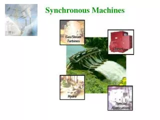
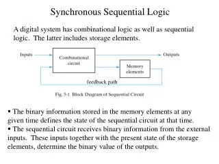
Sequential machines – Counters Exactly the same thing happens with larger synchronous sequential machines, they change state at the appropriate clock edge, and the conditions for the change are setup prior to the edge. The state change is determined by the control inputs and the current state of the machine (just like the T-type) For a counter this usually means control inputs that determine direction, or whether to reset, or the load a new starting value or change mode. There may be no control inputs, in which case the counter just moves from one state to another as the clock occurs. It is obviously vital to have the machine start in the correct state. Although I have discussed control inputs that only cause action at the clock edge, it is common to provide some asynchronous control inputs – just to be used on powerup. Hence most a reset input may be provided that causes the action to occur immediately, without waiting for a clock edge. It is vital that you do not overuse this function; only use it on powerup, let all other changes be synchronous. This really matters when we couple state machines together or are trying to use automatic test equipment to test devices, or even when simulating to give consistent results
Sequential Synchronous Counters ‘0’ ‘0’ ‘1’ ‘0’ ‘1’ ‘0’ The circuit above is a synchronous sequential machine that is a binary counter. It counts from 0 to 15, but the principle works for n flip-flops where the count will go from 0 to 2^n-1 and n >2. To understand how it works; imagine a starting value in all 4 flip-flops – “0101” this is its state. Note that this is written as Q3Q2Q1Q0 as natural binary. The circuit has Q0 on the left however. The conditions before the clock are that T0=‘1’ (always) , so the Q0 output will (always) toggle, Q0 WILL goto a ‘0’, it is currently ‘1’ T1=‘1’ since Q0=‘1’ currently T2= 0 since Q1 is a ‘0’ currently AND T1 is currently ‘1’ (it is connected to Q0) T3 = 0 since Q2 AND T2 is (1 AND 0) Hence the first 2 flip-flops will toggle and the second two will hold “0101” - > “0110 i.e 5->6
Sequential Synchronous Counters It can be constructive to consider the changes of state as binary codes, before and after the clock Q3Q2Q1Q0 | Q3Q2Q1Q0 0 0 0 0 | 0 0 0 1 after the clk move and then the next 0 0 0 1 | 0 0 1 0 state instantly becomes the present state and we slide down the 0 0 1 0 | 0 0 1 1 0 0 1 1 | 0 1 0 0 For example, we toggle 0 1 0 0 | 0 1 0 1 Q2 if Q1 is ‘1’ and about 0 1 0 1 | 0 1 1 0 to toggle – hence the 0 1 1 0 | 0 1 1 1 need for the AND gates 0 1 1 1 | 1 00 0 1 0 0 0 | 1 0 0 1 1 0 0 1 | 10 1 0 10 1 0 | 10 1 1 1 0 1 1 | 1 1 0 0 1 1 0 0 | 1 1 0 1 1 1 0 1 | 1 1 1 0 1 1 1 0 | 1 1 1 1 1 1 1 1 | 0 0 0 0 These are tedious to work through And a more general purpose design Method is needed. This uses STATE DIAGRAMS, CRUDE STATE TABLES and FULL STATE TABLES.
State diagrams These illustrate the changes of state, and what the inputs have to be to cause a change to occur. Of course the changes only happen at the clock edge. They are useful visualisation tools, not really needed for counters since these have simple changes. They are also useful to allow conversion to a tabular format to allow more formal design. There are two types (Moore or Mealy), but in general we need to; Name the states with a human readable, meaningful name, for counters this is trivial and we usually use A,B,C… or s0, s1,s2, etc. Label every arrow leaving a state with an input pattern, if there is one input then there might be two arrows leaving a state, one labelled ‘1’ and one labelled ‘0’. It is allowed to loop back so that you leave state A and loop back to state A – this is a HOLD action . If there are 2 inputs there are 4 possible arrow condition, you can simplify arrow labelling, for example if you want to change state when an input is ‘0’ or ‘1’ then label it as ‘X’ meaning “don’t care” Outputs can be put inside the state bubble or attached to the input labels. These are known as Moore or Mealy state machines, ignore this for now as counters are usually Moore types
State diagrams In general state machines can have states that are not the output. For example a digital keypad lock has one output, possibly two if an alarm is to sound if a bad key is typed in. If we need to enter the code 142 into a digital lock then there is a “PENDING” state, a “DIG1OK” state, a “DIG2OK” state, a “DIG3OK” state and a state where it opens, there might be a state called “ALARM” Ignore the details of designing such a machine for now except to note we might give each named state a binary code such as “000”,”001”, “010”, “011”, .. etc. Different designers might implement the outputs at slightly different times and variations in state codes do affect system cost -this is called STATE ASSIGNMENT. The good news is that for counter design we simply pick the desired outputs as are state codes and hence there is no state assignment decisions to be taken. The only essential criteria to be met is that each state MUST have a UNIQUE code. It must be possible to walk up to a state machine with a logic probe and tell what state it is in by recording the outputs of each flip-flop in the machine..
A ---------- 0001 1 1 1 1 Crude State table for this state diagram State diagram for an up/down counter 0 B ---------- 0010 0 0 C ---------- 0100 D ---------- 1000 0 Crude state tables should just have named states and are just a tabular form of the diagram
Full State Table Full state tables show what binary code you assign to each state, we could have used the output codes here but that would have needed 4 flip-flops, choosing straight natural binary means only needing 2 flip-flops. We will need a simple combinational circuit to generate our 4 outputs from the state code but this straightforward (and cheap). I do not require you to design any further, but a knowledge of state diagrams is useful…
One-Hot Design Method There is one design method that bypasses the need for state tables, the one-hot design method produces expensive designs but they are quick and easy. The rules are; You must use one D-type flip-flop per state ( a cost model might use 6p per flipflop!!!) You must use a state assignement of n-1 zeros and a single ‘1’ i.e for a six state machine {000001,000010,000100,001000,010000,100000} You will usually need output decoders to generate the actual outputs when you want them, the one-hot machine is great at moving you from one state to another, but it is up to you to generate the outputs You must powerup to the correct state, usually this means using PRESET on the first flip-flop and CLEAR on the remaining flip-flops. There are variations – ONE-HOTZ and TWO-HOT but I normally avoid them, also there are alternative ways of starting the machine… The design method is deceptively simple. You focus on the arrowheads entering each state. Write down an expression for each arrowhead, OR them together and that gives you the logic equation for that flip-flop.
One-Hot Design Method • Here we see 4 states, State A has 4 arrowheads arriving at it. Hence • A = A./I + B./I + C./I + D.I (2+2+2+2 + 4p = 12p) • B = A.I (2p) • C = B.I (2p) • D = D./I + C.I (2+2 + 2p = 6p) • And we need to generate the output • Z = D • The cost model presented earlier in class was 1p per input for any gate with 2 or more inputs and 6p per flipflop. Hence this design costs 22p for gates and 24p for flip-flops = 46p • An conventional design costs 29p (2 d-types and natural binary assignment)