Download
1 / 23
230 likes | 389 Views
Beam Monitoring in CMS Application of the BLM System to CMS. Alick Macpherson On behalf of the CMS Beam Conditions and Radiation Monitoring Group Institutes Involved: Auckland, Canterbury, CERN, DESY, Karlsruhe, Princeton, Rutgers, Tennessee, UCLA.

E N D
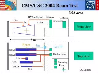
Beam Monitoring in CMS Application of the BLM System to CMS Alick Macpherson On behalf of the CMS Beam Conditions and Radiation Monitoring Group Institutes Involved: Auckland, Canterbury, CERN, DESY, Karlsruhe, Princeton, Rutgers, Tennessee, UCLA
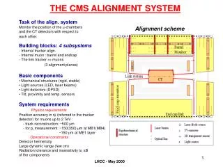
CMS BRM: Beam Conditions + Radiation Monitoring Group Remit Provide monitoring of the beam-induced radiation field within the UXC55 cavern and the adjacent straight sections. Provide real-time fast diagnosis of beam conditions and initiate protection procedures in the advent of dangerous conditions for the CMS detector • System features must include: • Active whenever there is beam in LHC • Ability to initiate beam aborts • Provision of warning & abort signals to CMS subdetectors • Postmortem reporting • Provision of online and offline beam diagnostic information to CMS and LHC • Bench-marking of integrated dose and activation level calculations • Integration of all online beam diagnostic information (including subdetectors). • Updating at ≥1 Hz
BRM Subsystems: The Prioritized List PHASE 1: Installed for Startup • RADMON • Extension of LHC wide radiation monitoring system. 18 monitors in CMS • BCM2: Diamond leakage current monitor at rear of HF • Readout as extension of the LHC Beam Loss Monitor (BLM) system • Commissioned against BLM monitors in Long Straight Section • Output to CCC and CMSCR • Input into beam abort (after commissioning against LHC BLM) • BCM1L: Diamond leakage current monitor in tracker vol. (close to beampipe) • No FE electronics • Commissioned in conjunction with BCM2.Output to CCC and CMSCR • Input into beam abort after commissioning (against BCM2) • BSC: Beam Scintillator Counters • Large area scintillator tiles on the front of HF • Output to CMSCR • Initially only a monitoring system • BPTX • Output to CMSCR. Initially only for monitoring • BCM1F: Diamond + fast amplifier for bunch by bunch monitoring • Installed prior to First physics run (or earlier) • Output to CMSCR • Initially only a monitoring system Upgrade systems under consideration for 2008/9 • Upgraded BSC (position, robustness, technical trigger) • PLT: Pixel Luminosity Telescope (not yet endorsed). • Would also be a beam diagnostic device Increased complexity/deviation from standard LHC interfaces PHASE 2 CCC=CERN Central Control RM CMSCR=CMS Control Rm PHASE 3
BRM Subsystem Summary Increased time resolution All online systems read on when machine operational and possibility of beam in LHC Systems are independent of CMS DAQ
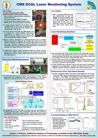
3 3 1 1 2 2 BCM: Beam Conditions Monitors CMS BCM Units BCM1L: Leakage current monitor Location: z=±1.9m, r=4.5cm 4 stations in Sensor: 1cm2 PCVD Diamond Readout: 100kHz No front end electronics BCM1F: Fast BCM unit Location: z=±1.9m, r=4.3cm 4 stations in Sensor: Single Crystal Diamond Electronics: Analog+ optical Readout: bunch by bunch (Asynch) BCM2: Leakage current monitor Location: z=± 14.4m, r=29cm, 5cm 8 stations in Sensor: 1cm2 PCVD Diamond Readout: ~20kHz Sensors shielded from IP Off detectors electronics 2 Sensor Locations, 3 Monitoring Timescales
Full BCM Readout Chains • Baseline systems on track • BCM2 readout chain • Full chain validated [sensor to backend readout]: Karlsruhe Aug 06 • BCM1L readout chain • Custom Mezzanine card tested: Based on Tevatron design • Prototype of chain from sensor to VME backplane expected January 07 • Interface: • Interface teststand (Bat 376-R-009) with interface to CCC: operational by 1/12/06 • Implication: Will complete full slice test by February 07 => BCM1, BCM2 readout chain + interface to CMSCR and CCC VME Crates Front end Interface Network and hardwired connection to CMS and CCC
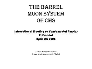
to control room Example: CMS BCM Sensors in CDF- Online Monitoring Plots Polycrystalline diamond At diff radii (3, 10.7cm) • CMS BCM Sensors in CDF: • Sensors + electronics in realistic hadron collider environ • Cross calibrate with existing CDF beam monitoring (BLM and diamond based) • Uses 20us Sampling Poly vs single ECDF, ESCMS: same location
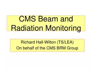
Display BRM Interface: Schematic view CMS DB BCM1/BCM2 Radmon BRM - PC ? x1/x2 DCS VME PowerPC PowerPC PowerPC Conditions DB BSC BCM Radmon • Info logging from BRM • 1s sum • capture • - post mortem on abort or LHC BIC CCC - DB DIP LHC-expt data exchange (defined by LEADE)
BCM in detail: What’s envisaged • Three locations • BCM1: Inside the CMS detector, z=1.8m from the IP, r=4.8cm • BCM2: Outside the central detector ( z= 14.365 m) • Two locations • Shielded from IP (r= 29cm) • As close as possible to Beampipe (r=5cm) • Outside CMS: Place diamond sensor next to a BLM unit in LSS • Calibration cross check • Readout as per tunnel card and full BLM system • All locations: • monitor diamond leakage current synthetic polycrystalline diamond sensor • Warning/alarm abort thresholds to be CMS configurable • Readout: • BCM2 + outside CMS: • Standard BLM readout ( Tunnel card to DAB board to data base) • Exactly the same readout and reporting structure • BCM1: • BLM readout from DAB card onwards. • Sub orbit monitoring (~10us) synchronized to orbit Clock • No tunnel card • Custom mezzanine card on DAB board. Uses BLM interface and reporting structure • Post-mortem and monitoring data • Reporting mechanism unchanged from BLM system ie CMW/FESA • Data stored in BLM database (just like other BLM data)
Components: What’s needed CMS_BCM Interface Lab (Bat 376-R-009 ): Teststand for Interface to CMSCR/CCC BCM1 Programme (Princeton): Development site for BCM1 BCM2 test programme (Karlsruhe): Based on BLM_USB prototype
Timing Cards: What’s needed – part II • Modules needed for complete BCM1L and BCM2 system: • 2 CTRV • 2 BOBR • Gives BCM crates full functionality and compatibility of the BLM system. • CTRV modules were not foreseen for CMS. This is a new purchase request. • Cards to be located in existing BCM1L and BCM2 crates • Exactly the same configuration as for the BLM system. • No new software is foreseen for these timing modules, • will be used in exactly the same way as for the BLM system. • Signals into CTRV cards • Should come directly from machine racks in CMS • GMT comes into S1E08 of the CMS USC • Optical signals into BOBR: Ideally should come directly in from machine. • => split off from main input into CMS. • Question over routing: Need to ensure this main input into CMS is on “safe power” • Needs some discussions within CMS.
Maintenance + Software: What makes sense • All hardware/software taken from machine group • Ideally, treated as any other BLM system as regards maintenance and upgrades • Any additional hardware that is added by the BRM group • MUST be fully compatible with the BLM system • Maintenance is the responsibility of CMS_BCM group. • Timing signals • responsibility of machine group up to the unit in the crate • ie CTRV and BOBR modules. • Software/Firmware: Where possible use BLM system without changes • Changes only when absolutely necessary. • All software which has been changed becomes responsibility of CMS_BCM. • Wherever changes are needed, they will be implemented by the BRM group • However would appreciate consultation with the expertise in BLM/BI/CO groups • It is not foreseen to request any special software from the BLM/Controls groups
Modifications/Additions: What we would like • Tunnel Card Low Voltage power supplies. • Will not use power supplies due transformers in to fringe field of CMS magnet => supply low voltage directly to tunnel card regulators via long cable • Tested tunnel card and regulators to 3 kGauss • HV supplies • Presently investigating options: Integrate supplies with our CAEN controller • General Firmware • Requesting that “capture data” functionality be available in baseline firmware. • Capture data = diagnostic postmortem data without triggering beam abort • Purpose: Full diagnostics calibration and commissioning • BCM2 • No modifications or additions requested • BCM1 • CMS Custom mezzanine card that mounts onto DAB. CMS responsibility. • No optical link => No tunnel card • Firmware • Custom mezzanine card firmware being developed. CMS responsibility. • Where possible/feasible, use standard BLM firmware for DAB and interface to CCC • At this stage no requests for modification foreseen
ABORT signal: What we foresee CMS_BRM is responsible for CMS detector input to the BIC • This means that we generate the input to CMS detector CIBU • We need to confirm the CIBU interface with AB_CO. Location of patch panel for CIBU interface • USC55; area S1. Rack S1E08. By design, BCM2 rack is S1F08 • Observations: Both racks on generator + UPS power => "safe" operation guaranteed in event of power cut to CMS services/cavern. Operations and the ABORT signal • CMS-Detector input is an integral part of the detector safety system => Must be active whenever there is a possibility of beam in the machine • Operation on Day 1: • input into BIC (via CIBU) to be via BLM COM card in BCM2 crate • Exactly the same ABORT functionality as for the BLM system. • => BCM2 is baseline for initial system • Commissioning is in line with BLM commissioning • Operation ASAP after Day 1 (Once initial running conditions assessed) • Add CMS specific combiner card. • Combines BCM2 and BCM1 signals, issue ABORTs • This CMS combiner is in addition to the BLM combiner • CMS_BCM is responsible for design, commissioning, maintenance of this card • The CMS combiner initially runs in parallel. • output monitored =>performance and reliability cross checked.
Summary: What we are asking for • Endorse proposal of CMS_BCM to use BLM system within CMS • CMS_BCM to be considered as an extension of BLM system into Pt 5 • CMS BCM system is to be based on BLM hardware and firmware • CMS BCM data reporting and storage to be done in the same way as BLM data. • Ensures BLM-consistent reporting and tracking of CMS beam conditions to CCC • Recognize that: • the BCM2 is fully based on the BLM system • the BCM1 system, while based on the BLM, requires a custom mezzanine card. • The CMS_BCM inputs into the CMS experiment input of the Pt5 BIC • The warning/alarm/abort thresholds are to be CMS configurable. • Modifications/additions to the BLM framework to limited to a minimum • Allow CMS_BCM to purchase the necessary BLM hardware • Equipment list discussed to be approved by Bernd Dehning • Where possible we would hope to purchase through standard AB_BI channels
Summary: What we are asking for – part II • Endorse request for timing cards • Request is made so that CMS_BCM can: • maintain full BLM functionality • Provide a full set of diagnostic tools to CMS => comprehensive reporting of Pt 5 beam and bkgd conditions as function of machine operation. • Endorse proposal for cross calibration sensor outside CMS • Permit continued discussion and development between BLM and CMS_BCM • Development and testing of hardware and firmware • Operations and data logging • Take note: a clear monitoring program is being put in place for CMS • This program is focused on the commissioning and early running • Will rely on open feedback and discussion between CMS and the LHC • Will benefit from close working relations and consultation with BLM, AB_BI, AB_CO, and LHC_OP • In all aspects the CMS_BCM is flexible wrt BLM/BI constraints, as we very much want to integrate and take full advantage of the BLM system.
BCM: Monitoring Timescales BCM2: monitors leakage current on half-orbit scale • LHC-standard readout hardware from LHC Beam Loss Monitor (BLM) group • Replaced ionization chamber with polycrystalline diamond (10x10x0.4mm) • Sampling time: 40 us • Monitoring time scales: 12 staggered buffers to cover 40us to 100s history BCM1L: monitors leakage current on sub-orbit scale • Synchronizes with orbit marker • User configurable sub-orbit sampling scheme: (4us minimum) • Statistical measurement of conditions at user specified positions in orbit • Sub-orbit monitoring averaged and passed to std BCM2 staggered buffer readout • Dedicated sampling of beam abort gap BCM1L Sampling Scheme
BCM1_ L Leakage current measurement Sensor: polycrystalline diamond Fine for leakage current 10x10x0.4mm 7000e-/MIP In : 4 BCM units No front end electronics Bias voltage: 400V (nominal) Sensor orientation set by need for ExB avoid anomalous leakage currents No direct cooling allowed/needed BCM1 Unit • Modular design • Sensors hermetically sealed • Accommodates gross mis- • alignment of beampipe (2mm) • Rad hard of TiW metallisation • validated at PSI and Karlsruhe BCM1_ F • Bunch by bunch measurement • Sensor: Single crystal diamond • Needed for single MIP detection • 5x5x0.4mm • 18000e-/MIP • In : 4 BCM units • Dedicated front end electronics • rad hard amplifier -> optohybrid • Bias voltage: ~100V (nominal) • Limited space for front end electronics • No direct cooling allowed/needed
RADMON • Locations 18 Monitors deployed around CMS (UXC +USC)
BSC: Beam Scintillator Counters Functionality • Provide an independent bunch occupation monitor. • Abort gap monitoring • Provide a technical trigger source • independently supply “better than zero-bias” trigger • Halo muon trigger for Tracker alignment Readout: • Mounted on front of HF, readout over long cables to USC. • Simple standalone system: No front end electronics • ADC & discriminator + TDC readout (t1,t2,Dt). Common stop • Same back end as BCM1F • Output to CMS: statistical measurements • Rate monitoring on sub orbit scales • Relative time measurements: incoming bkgd to outgoing collision products + bkgd CMS: display similar to ZEUS example • Cross-sectional Areas • HF = 5.6m2 TK = 3.8m2 • BSC paddles =0.6m2 BSC =1.1m2 • Ratios • BSC_Paddles/TK =17%; BSC/HF =20% BSC Paddles BSC Disks