Download
1 / 18
180 likes | 277 Views
Object-oriented modeling Statechart diagrams. Karolina Muszyńska. Based on : S. Wrycza, B. Marcinkowski, K. Wyrzykowski „Język UML 2.0 w modelowaniu SI”. Object Modeling. Dynamic view – statechart diagrams role basic concepts advanced concepts examples. Statechart Diagrams –role.

E N D
Object-oriented modelingStatechart diagrams Karolina Muszyńska Based on: S. Wrycza, B. Marcinkowski, K. Wyrzykowski „Język UML 2.0 w modelowaniu SI”
Object Modeling • Dynamic view – statechart diagrams • role • basic concepts • advanced concepts • examples
Statechart Diagrams –role Statechart diagram,also called state machine,is one of the five UML diagrams used to model dynamic nature of a system. It defines different states of an object during its lifetime and these states are changed by events. Statechart diagram describes the flow of control from one state to another state. States are defined as a condition in which an object exists and it changes when some event is triggered Statechart diagrams are useful to model reactive systems. Reactive system can be defined as a system that responds to external or internal events.
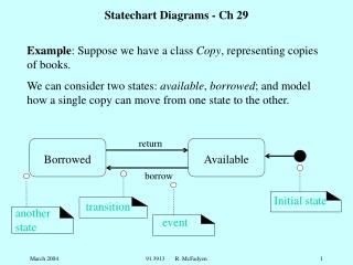
Statechart Diagrams –basic concepts State - is a circumstance in which an object is situated in its life cycle, when it meets a certain condition, performs an operation or waits for an event to occur. Transition is a relationship between two states, indicating that the object being in the first state will perform certain actions and move to the other state, whenever a specific event occurs and certain conditions are met. Initial state is the initiation of the statechart diagram Final state is the termination of the statechart diagram
Statechart Diagrams –basic concepts Initial state Transition State Final state
Statechart Diagrams – advanced concepts Sections of graphical symbol of state: • name section – place for the state name • internal operations section - lists the internal operations performed when an object achieves a certain state. Type of the internal operation is identified by one of the keywords: • entry - an operation automatically performed on the object the moment it achieves the state (there may be only one within a state), • exit - operation performed when an object leaves the state (there may be only one within a state), • do - operation performed continuously on the object being in a given state (there can be many such operation within a state)
StatechartDiagrams – advanced concepts Sections of graphical symbol of state: internal transitions section - indicates specific cases of transitions, execution of which does not lead to a change of state. Internal transitions do not have their own graphical symbol but are specified in the state area decomposition section – informs about decomposition of the state into sub-states
Statechart Diagrams – advanced concepts Name section Internal operations section Decomposition section
StatechartDiagrams – advanced concepts Classification of states: Simple state - a state that does not contain any sub-states or orthogonal regions Composite state - a state, which contains either sub-states or is divided into orthogonal regions Sub-state – a state machine into which a composite state is decomposed (a sub-state can be either direct or indirect depending on the level of decomposition)
StatechartDiagrams – advanced concepts Substate of the decomposed composite state ‘Received’
Statechart Diagrams – advanced concepts Orthogonal region – concept used for showing states and transitions within in a composite state, which are activated concurrently. Transitions can cross composite states boundaries. All orthogonal regions must be realized in order for the state to be completed. Pseudo-state is an abstract category of statechart diagram modeling, which allows for organizing complex transitions by the use of fork node, join node, junction, decision node, termination, etc.
Statechart Diagrams – advanced concepts Pseudo-state (junction point)
Statechart Diagrams – advanced concepts Orthogonal region
Statechart Diagrams – advanced concepts Transition types: • simple - occurring between the source and target state, • return - where the source and target states are the same state, • internal – constituting one of the elements of a state, • local - indicating transitions between any sub-states of a composite state, • external - leaving a composite state and directed to another state or pseudo-state, • high level or group - leaving composite states and indicating the necessity of leaving all sub-states of this composite state before transition, • complex – chain of transitions joined or forked, linked by a junction or decision node, • automatic – without any associated event or condition.
Statechart Diagrams – advanced concepts Types of state machines: Protocol state machines- concentrate on a specific object and present available and permitted transitions between the states of this object Behavioral state machines- present transitions between states of many objects in a wider context of system, subsystem or use case behavior
Statechart Diagrams – advanced concepts • Events - stimuli sent by objects, which initiate transitions from one state to another • There are five types of events: • signal – asynchronous stimulus transmitted between two objects (e.g. signal from a sensor), • call event – calling operations of one object by another object (e.g. login, register), • time event – event, which occurs after a certain period of time (e.g. after (3 hrs.)), • status change event – event, which occurs at a certain point of time (e.g. when (date = 1 July) • deferred event – event, which is not supported within a given state but added to the deferred events queue (e.g. summary of Receivables /defer)
Example of a protocol state machine describing EXAM class object states
Building a Statechart Diagram • Determination of the type of created state machine and identification of objects • Identification of possible states of a state machine • Determination of the hierarchy of states, sub-states and orthogonal regions • Linking the states and their sub-states with transitions • Application of adequate pseudo-states